
You are using an out of date browser. It may not display this or other websites correctly.
You should upgrade or use an alternative browser.
You should upgrade or use an alternative browser.
Radiator thermostat switch wiring diagram
- Thread starter petex19
- Start date
petex19
True Classic
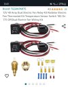
Do these kits work with the upgraded aluminum radiator and dual fans for our cars? Can the sensor be connected to the cylinder head for engagement and wired to the fans?Does anyone have an easy to follow wiring diagram for the radiator thermostat switch?
I need a complete diagram restoring factory operation of radiator as it was designed.
Attachments
Last edited:
Bjorn Nilson
True Classic
I have a an alu rad with dual Spal fans with no mods on the electrical side and it is working fine. Modern fans doesn't draw that much current so no mods with extra relays etc needed iMO.Do these kits work with the upgraded aluminum radiator and dual fans for our cars? Can the sensor be connected to the cylinder head for engagement and wired to the fans?
kmead
Old enough to know better
The X already has a relay for the one fan. If your car has AC then it has a relay for each fan. As you have a 1984 all the wiring to add the second fan and a relay is already present. You don’t need one of those ‘kits’.Do these kits work with the upgraded aluminum radiator and dual fans for our cars? Can the sensor be connected to the cylinder head for engagement and wired to the fans?
You don’t want the fans to be related to the cylinder head as they would run all the time when they don’t need to, particularly in Canada…
Dr.Jeff
True Classic
I realize you want to retain the stock wiring configuration, so this is just for the sake of discussion.
With two fans you can also use a dual-temperature fan switch (the temp sensor that goes into the radiator) to control the fans in two stages. This allows only one fan to run until the system temperature reaches a specified level, then the second fan kicks in. The two-stage (dual-temp) switch is a easy swap; VW used the exact same size switch available in single or two-speed versions and various temp settings, which is a direct bolt in for the X's radiator. However this requires a slightly different wiring arrangement to connect the fans.
With two fans you can also use a dual-temperature fan switch (the temp sensor that goes into the radiator) to control the fans in two stages. This allows only one fan to run until the system temperature reaches a specified level, then the second fan kicks in. The two-stage (dual-temp) switch is a easy swap; VW used the exact same size switch available in single or two-speed versions and various temp settings, which is a direct bolt in for the X's radiator. However this requires a slightly different wiring arrangement to connect the fans.
petex19
True Classic
I'm very interested in this two stage dual temp switch setup. Do you have a wiring diagram? I'm not concerned with keeping wiring all original. Whatever is easiest to wire up. I'd buy a wiring kit and the relays if that was easier. ThanksI realize you want to retain the stock wiring configuration, so this is just for the sake of discussion.
With two fans you can also use a dual-temperature fan switch (the temp sensor that goes into the radiator) to control the fans in two stages. This allows only one fan to run until the system temperature reaches a specified level, then the second fan kicks in. The two-stage (dual-temp) switch is a easy swap; VW used the exact same size switch available in single or two-speed versions and various temp settings, which is a direct bolt in for the X's radiator. However this requires a slightly different wiring arrangement to connect the fans.
kmead
Old enough to know better
The factory wiring diagram is quite clear on how to wire it, hasn't really changed in the years since the first X was built. Some wiring colors may have changed. As you have a 1984 car the relay is next to the fuse block so there are really only two wires which run from the fuse tray to the front of the car on a non AC car. One wire runs to the thermoswitch and the other goes to the fan. Both carry power.Does anyone have an easy to follow wiring diagram for the radiator thermostat switch?
I need a complete diagram restoring factory operation of radiator as it was designed.
OE fans use 110w according to the owners manual, it shares its 16 amp fuse with the relay for the horns. Personally I prefer the factory fans over the ones you generally get unless they are Spal fans and you can verify their origin.
The thermoswitch is the weak point in the system as they tend to fail. The rest of the system is simple and reliable.
In short:
- There is a fuse which is on an unswitched circuit run directly to the battery.
- The fuse feeds a relay next to the fuse block on pin 30 of the relay.
- There is wire switched by the ignition switch which goes to the 86 pin on the relay to provide power to the relays electromagnet.
- From the relay you have a wire going from the 85 pin to the thermoswitch on the radiator, this is the wire which provides ground to the relay when the thermoswitch on the radiator closes.
- The second wire on the thermoswitch goes to a ground bloom in the drivers side headlight bucket.
- When the thermoswitch closes, it grounds the relay and power flows from the 30 pin to the 87 pin of the relay and from there to the radiator fan which has a second black ground wire which goes to the same ground bloom in the drivers headlight bucket.
If you have an AC car it is possible to control that fan with a different thermoswitch which has two switches inside and can control two relays. One could also modify the wiring for the both fans to come on at the same time using the same thermoswitch you have now.
You can also add a switch in the passenger compartment to provide a ground to the relay so you can turn the fan or fans on at will.
The attached page is from the electrical diagnostic manual available from the Wiki and is something you should download and print.
The wiring diagram for a 1981 car is effectively the same as your car.
The 1974 diagram is a good one as it shows the general run of the wiring system, the differences lie in location of components and later cars have more electrical features. On an early car the relays for the fan and the horn live in the drivers side headlight bucket area which is not a good environment for electrical widgets.
Understand in any case the wiring colors can and will be different on many cars.
Attachments
kmead
Old enough to know better
A wiring kit is not easier. Using the resources in the car already would require some very minor rewiring.I'm very interested in this two stage dual temp switch setup. Do you have a wiring diagram? I'm not concerned with keeping wiring all original. Whatever is easiest to wire up. I'd buy a wiring kit and the relays if that was easier. Thanks
Does your car already have AC?
Last edited:
petex19
True Classic
My car is an a/c car originally. The a/C has been removed.A wiring kit is not easier. Using the resources in the car already would require some very minor rewiring.
Does your car already have AC?
petex19
True Classic
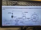
I took a picture of this dual fan wiring diagram. I believe this is what you described?A wiring kit is not easier. Using the resources in the car already would require some very minor rewiring.
Does your car already have AC?
Attachments
kmead
Old enough to know better
Not exactly. Yes that is the general function, in the case of your car most of the wiring to complete this was installed at the factory.I took a picture of this dual fan wiring diagram. I believe this is what you described?
Is your car AC or non AC?
If not AC, if you go to page 9 of the 1981 wiring diagram it shows the various wires, sensors and relays.
To enable this you need to locate the black wire which would normally run to the AC condenser fan thermoswitch. This wire will now go to the third pin on the new VW dual temp thermoswitch instead. You will then need to get an additional 4 pin standard relay to put in the AC condenser fan position next to your fuse box and verify you have power to pin 30 when you install a 16 amp fuse in the AC fuse position O/13. You also need power at the 85 pin on the relay which comes from fuse A/1.
(If AC then you will need to go about this slightly differently with a jumper wire from the ground wire running to the existing AC Condenser fan thermoswitch over to the new VW thermoswitch. This wire will be attached to the wire which comes from the existing relay but before it reaches the AC Condenser fan thermoswitch. It won't need a diode as you want it to come on in either circumstance of either thermoswitch grounding.)
Correction to the last bit above, there is already a ground interconnect for the two relays so may not need to do the jumper. I have never seen an AC X in operation to know if when the cooling fan for the engine comes on if the AC fan also comes on at the same time. Someone who has a functioning system like @Dan Sarandrea (Phila) may be able to answer this.
Last edited:
Dr.Jeff
True Classic
Sorry I don't have a wire diagram for using a two-temp fan switch. But Karl just offered a excellent description of it in post #11. As he said, since you have a X originally equipped with AC then it should already be wired for two fans. However in that application the second fan is controlled by the AC circuit, not the radiator switch. So he described how to rearrange the existing wires (for the second "AC" fan) to go to the VW radiator switch.I'm very interested in this two stage dual temp switch setup. Do you have a wiring diagram? I'm not concerned with keeping wiring all original. Whatever is easiest to wire up. I'd buy a wiring kit and the relays if that was easier. Thanks
The dual-temp VW radiator switch was also discussed more in prior threads. Here is one, read through it to get a better idea of how it works:
Couple of radiator fan questions
My car is a '79 Non A/C car. Don't think my fan is working at all. When warmed up, about where is the temp gauge needle supposed to be? Mine is a bit above the 190 mark on the gauge. How do you know when the rad fan is on? Can you hear it running when driving the car? Should the fan continue...
xwebforums.com
petex19
True Classic
Great amount of information. Many years ago I noticed my fans were never coming on. I didn't know how to fix it so I wired the two fans to a toggle switch in the car.A wiring kit is not easier. Using the resources in the car already would require some very minor rewiring.
Does your car already have AC?
I don't even remember exactly how I wired them. I just know that they operate with ignition on or off so I know they are wired to battery 12v. I never bought any aftermarket wiring or relays so it must be tied into factory wiring.
All the videos I have watched are pretty straight forward on wiring two electric radiator fans. Is there a reason why a good quality kit complete with relays isn't a good idea? I no longer have the A/C connected in the car. All the A/C parts were removed decades ago.
Dr.Jeff
True Classic
The point about it originally being a AC car isn't so much the AC components themselves, but the wiring to the second fan that was AC specific. In other words, you already have most of the needed wiring in place and only need to do a little rerouting of some of it to get the task done. Makes the job much easier.
That is also why a aftermarket wiring kit really isn't needed. Aside from the actual relay itself there really isn't anything you will need from it. Seems more economical to buy just a basic relay. Then you can carry out the changes that Karl outlined earlier.
That is also why a aftermarket wiring kit really isn't needed. Aside from the actual relay itself there really isn't anything you will need from it. Seems more economical to buy just a basic relay. Then you can carry out the changes that Karl outlined earlier.
kmead
Old enough to know better
Unless you pulled all the AC related wiring out of the fuse box and the nose of the car you would have all the wiring needed.Great amount of information. Many years ago I noticed my fans were never coming on. I didn't know how to fix it so I wired the two fans to a toggle switch in the car.
I don't even remember exactly how I wired them. I just know that they operate with ignition on or off so I know they are wired to battery 12v. I never bought any aftermarket wiring or relays so it must be tied into factory wiring.
All the videos I have watched are pretty straight forward on wiring two electric radiator fans. Is there a reason why a good quality kit complete with relays isn't a good idea? I no longer have the A/C connected in the car. All the A/C parts were removed decades ago.
What you may have done back whenever is provided an alternate ground through the switch for the two existing relays to run the two fans at will. I would look at what you have, take some pics and make a simple diagram of what you have already. If your fans are working then you clearly have wiring from the passenger compartment to the fans.
In my experience running additional wiring in an X is not fun particularly from the fuse box area forward.