Ellychiprout
1986 Time Traveler X
I need the alternator cooling duct for my 1986 X. Anyone has one to sell? Or ideas for replacing it with something that looks stock. Thanks all !!!


The NAPA item I ordered from a local NAPA store looked perfect in the catalog, but when it arrived, it had a black paper exterior rather than a silver aluminized exterior.
Gates #28089 is very close to the OEM ducting.
Example: http://www.ebay.com/itm/Gates-28089-Heater-Duct-Hose-/260876235266
It's 1-1/2" inside dia x 36" long
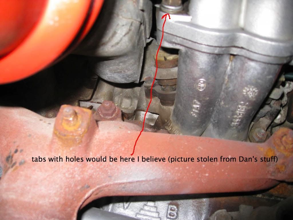
Thanks for the help. Still confused. The metal duct has two tabs with holes to pass bolts through. Where do these tabs go? In the two studs that protrude in the center between the intake runners? It is very difficult to position the duct so it fits in those studs. Do the air holes in the final assembly position point down?