Any internal Computer Diagnostics?

jake

True Classic
What Happened and what I have done: I was driving at low speed and the car just died. It would crank faster than normal and I suspected fuel injectors not working. Towed it home and went through the l-jet diag. Everything checks good, no voltage at injectors. First start of the day the cold start works for a second and car fires then nothing until the thermo time switch cools. I have the pulse at the computer terminal and no resistance to injectors at computer connector. So from the diag the computer is bad.

I ordered a new computer and waiting for it to show up. So I decided that maybe a cap or burnt trace might be in the computer. I opened it up and nothing looks bad.

So my question is:
Any common failures known in the computer boards?

https://imgur.com/izTIQ7S
https://imgur.com/KQmmy2X
https://imgur.com/gHYqaYF
https://imgur.com/QFtOe2M
https://imgur.com/GNqFyRK
https://imgur.com/REnIpxZ
https://imgur.com/i03XqDy
https://imgur.com/sFpyVBP
 
Honestly I've never known a Bosch computer to actually go bad since they started making them. I'm sure it could be possible, but I rather doubt that was the cause of your issue. Have you checked for continuity on each wire between the master connector (at the ECU) and the other ends? Wire harness failures can happen internally anywhere along the path, as well as at any/all connections. Sounds like the dual relay checked good(?), but how about all of the contacts for the relay, and connectors to everything else for that matter? Grounds? Lots of reasons for your condition to happen. Following the diagnostic manual was the right thing to do. But it was written when everything was new and sometimes it assumes things like wires can't go bad. Unfortunately over the years corrosion can happen ANYWHERE.

I'm not necessarily implying you are wrong about the computer being bad, it very well could be. I've just never found a verified case where that was true. I have seen where removing and reinstalling the master connector to it solved such a problem (i.e. the contacts were corroded), and therefore replacing the ECU seemed to fix it (but with further analysis that really wasn't the case). So if the new one does not fix the problem, then consider less obvious reasons. Please let us know what happens, I'd love to find out that you are right and the ECU failed.
 
Yeah, I forgot to mention that i redid all the grounds and terminals prior to doing the l-jet diag checklist. i get no resistance to injectors from the computer. All the voltage from the double relay checks good. Swapped out another double relay from my stockpile and same results.

It's possible there is a ground (replaced grounds/terminals at top of engine and by fuel filter) that I don't know of somewhere or something at the terminal for supply . I don't recall any checks at the terminal for voltage other than the pulse.

from my notes:
no volts at injector connector
term pin 8 to 9 200 ohms
12v at term 88z key off
12v at term 86c key on
85 ground good
86a 88b and 88e 12v key on
no resistance on term 5,16,17
term 1 pulse
term 1-5 1-16 1-17 pulse voltage .2v correct? lights test light pulse
 
Last edited:
If I recall correctly, the ECU pulses the ground to the Injectors, with constant voltage to them.
But one main point I was making is the possibly of a fault within the wires themselves. Just recently another member found that to be the cause of faulty injector function.
 
The one thing that stood out to me is that you said it cranks faster than normal. This, to me, might mean lost of compression. Did you verify the timing belt is intact? Did you do a compression test?
 
compression is fine. checked timing and no issues there. cranks faster than normal due to no gas to compress. it will start with cold start injector every time it's ready.

I guess i need to know what pins the injectors are on the terminal and if there is any grounds i'm missing other than top of engine or ground bloom by fuel filter?
 
Last edited:
You say the “diag is the computer is bad”.

How did you arrive at that diagnosis? Did you follow the Bosch fuel injection trouble shooting manual which is available here on the forum wiki?

As stated previously the computers are very reliable and rarely actually fail.

Power to the injectors comes from the dual relay. It is outputting power to the injectors? Is the separate inline fuse good? Is the red with black exciter wire from the starter in place on the starter? The injectors should be hot anytime the ignition switch is on if everything is working properly. The ECU grounds the injectors so a measurement at the pins of the injector tells you very little.

I have included the wiring for the overall system and the injection system itself courtesy of the Mira site.
 

Attachments

  • 80Wiring,10.pdf
    988 KB · Views: 160
  • 80Wiring,02.pdf
    1 MB · Views: 115
You say the “diag is the computer is bad”.

How did you arrive at that diagnosis? Did you follow the Bosch fuel injection trouble shooting manual which is available here on the forum wiki?

As stated previously the computers are very reliable and rarely actually fail.

Power to the injectors comes from the dual relay. It is outputting power to the injectors? Is the separate inline fuse good? Is the red with black exciter wire from the starter in place on the starter? The injectors should be hot anytime the ignition switch is on if everything is working properly. The ECU grounds the injectors so a measurement at the pins of the injector tells you very little.

I have included the wiring for the overall system and the injection system itself courtesy of the Mira site.
http://www.type17.ch/downloads/Injection/Bosch - L-Jet - Troubleshooting.pdf

thats a way better diagram than i could find. I was using this l-jet diag and did everything down to the bottom of page 12. separate inline fuse I had no knowledge of or the red and blck wire. I get voltage at the relay and none at the injectors. where is the fuse?
 
Last edited:
The double or dual relay have been known to fail. It has a circuit board inside which can have cold solder joints or other failures inside. It may be the issue or possibly the wire from the starter is off.

I have been wrong before and I will be wrong again.

Good luck

Karl
 
the third picture. on the bottom side of the PC board, I see like 10-40 un-soldered pin's just bent over ??
If you compare it with the first picture, you'll see that these are jumpers connecting traces on the top side to traces on the bottom side. Apparently the PCBs where made without vias, perhaps because of reliability concerns? Back in the days of tube radios, "No printed wiring boards" was advertised as a sign of quality.
 
using those diagrams that you posted.
brown and white wire:
has .2 v at ignition module? mine has been removed due to allison distributorless setup. testing male barrel connector (c20 on diagram)
12v at the double relay.
found inline fuse in the fuse panel area. (green holder with brown white wires both sides) fuse is good and appears to be before the relay and ignition module. This right? or am I looking at something wrong.
 
Yup that is right.

On the double relay, the connections for the injectors, are they hot when you are trying to start the car?

Anytime the ignition switch is on the injectors should have power.
 
Ecu should pulse ground for injectors , but I expect it would look for ign signal BEFORE allowing fuel, to prevent flooding and general splashing of fuel when not wanted. 80's Bosch L-Jet & LH used to suffer from internal/floating ground failures and the switching circuit that responds to the ign pulse failures. Not hard to see that happening here, esp if water has wicked into ECU from harness, which is a thing....
 
if water has wicked into ECU from harness, which is a thing
That's a good point; water inside a ECU will cause damage. Although the Bosch ECU's are well sealed (even at the connector), it can happen. For those of us out west where there isn't much risk of flooding this is extremely rare, but I imagine in other areas water ingress can be a problem. Jake, is there any evidence of water damage on the old ECU?
 
Well, there was some copper corrosion on the blade terminals. screws inside all had white oxidation. It had lived most it's life in rain or moist carports (280K miles). That is one of the reasons i redid the ground bloom and cam tower grounds first. What I don't know is if there are more ground points. I have not got a chance to go back out and do more checks due to company showing up. maybe later today I might get a chance after work. I got another computer in the mail but haven't hooked it up yet either. I do want to check a few more checks before I try that just in case there is something shorted/broken in wiring.
 
In general there are numerous grounding points all around the car. Some are single leads, others have multiple leads. Not all of them involve the FI system, but off the top of my head I don't recall exactly which ones do. I think if you follow the wire harness for the FI system (which has its own harness), then you will find all of the grounds. Also look at any/all connectors other than grounds, and clean them as well. The corrosion on the terminals is very common and often the cause of issues. The screws inside really won't have any effect, unless they also act as an electrical contact of some kind. It would be signs of water corrosion inside on the boards and leads that are important. However from the sounds of what you've said I doubt that is the case. I'm still thinking it will be an external issue in the wire harness and/or connectors. Also check the harness where it passes through the bulkhead between the spare tire well and the engine bay. I've seen the wires get chafed there and ground or cross feed.

Although the cold start valve sprays fuel, have you verified that the injectors will? Very unlikely for all 4 to have a problem at the same time, but I suppose it is possible for something to have blocked the fuel supply beyond the "Tee" for the cold start valve. While it is most likely an electrical issue, might as well rule out all other possibilities.
 
i have not pulled the injector or put voltage to it externally. I think i might be understanding the system a little more maybe. I noticed someone somewhere said if you check ac you get more voltage. before I was testing at the injector connector between the 2 terminals and had nothing. but if i test with just the key on and not cranking. either side of the injector connector to ground says 12v with just key on no crank. so the computer is controlling the ground for a hot on both sides and alternating it? sorry, not much time tonight to do many tests...
 
There's no alternation, all injectors spray at once; they pulse because the computer controls the grounds; changing the on/off duty cycle times to control fuel delivery, and fuel injection volume also is kept proportional by the pressure regulator; the computer's inputs are from the moving vane in the AFR, the engine speed (from the ignition box), the oxygen sensor (with a limp home mode when not present), and the engine temp sensor.
12v is present at the injectors when the key is on (not in the 'remove' position).
Pulsating DC acts like ac on a meter.
 
Download THIS ELECTRICAL MANUAL easy to read diagrams, not like the main manual spaghetti.

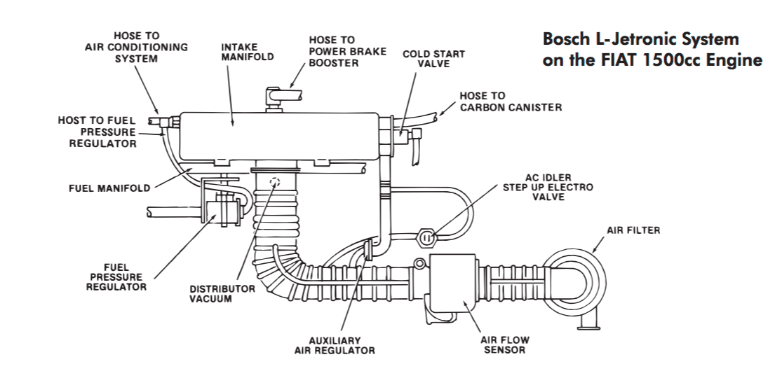
Component overview:

Screen-Shot-2018-06-22-at-9-13-04-PM.png
 
Back
Top