Rodger
True Classic
When I did my '81 K20 swap project, I created a custom wiring harness, utilizing the '85-88 Bertone fuse panel and a mostly complete wiring harness. I was fascinated by it as it was more than just a fuse panel. Many of the circuits that come from the front and back of the car just pass through the panel on their way to the instrument panel/dashboard, without ever going through one of the fuses. There are basically three main harnesses, a rear, front, and dashboard with everything running through the panel. I studied the wiring diagrams as well as checked a lot of the connections with my multimeter and eventually created a spreadsheet of all of the internal connections. Here is a Dropbox link to download the Excel file of all of the fuse box and relay connections. I was very tempted to try and take the one I had apart to see what it looked like inside, but didn't want to risk damaging it as they are hard to come by. There are three screws that hold it together, but taking those out doesn't get you very far as there are also six welded plastic rivets on the sides. I elected to leave them alone and not mess with it.
I acquired another fuse panel as well as the entire harness from another forum member here, for eventual use in my '79 restoration. With the acquisition of my '86 parts car, I now have another fuse panel and complete wiring harness to play with. The '86 panel was pretty dirty and two of the three screws that hold it together were pretty rusty, so I figured it must have gotten exposed to some water at some point. I decided I was going to break into this one so after I scrubbed it up, I drilled out the plastic rivets and pried it open.
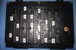
What I found was five, thin, flexible circuit panels inside, stacked on each other and then soldered to the fuse, relay, and harness connectors. The outer case is a one piece plastic molded part that folds up like a book with sides. There is also a plastic support frame inside that keeps the circuit panels tight against the connections. Here are a couple of pics of the inside. Definitely some signs of moisture corrosion on the solder joints.


I acquired another fuse panel as well as the entire harness from another forum member here, for eventual use in my '79 restoration. With the acquisition of my '86 parts car, I now have another fuse panel and complete wiring harness to play with. The '86 panel was pretty dirty and two of the three screws that hold it together were pretty rusty, so I figured it must have gotten exposed to some water at some point. I decided I was going to break into this one so after I scrubbed it up, I drilled out the plastic rivets and pried it open.
What I found was five, thin, flexible circuit panels inside, stacked on each other and then soldered to the fuse, relay, and harness connectors. The outer case is a one piece plastic molded part that folds up like a book with sides. There is also a plastic support frame inside that keeps the circuit panels tight against the connections. Here are a couple of pics of the inside. Definitely some signs of moisture corrosion on the solder joints.
Last edited: