Clock wiring circuit

Birdy

Daily Driver
Hi. I'm new here from the UK. Just trying to navigate my way around this forum so I'll introduce myself properly another day.

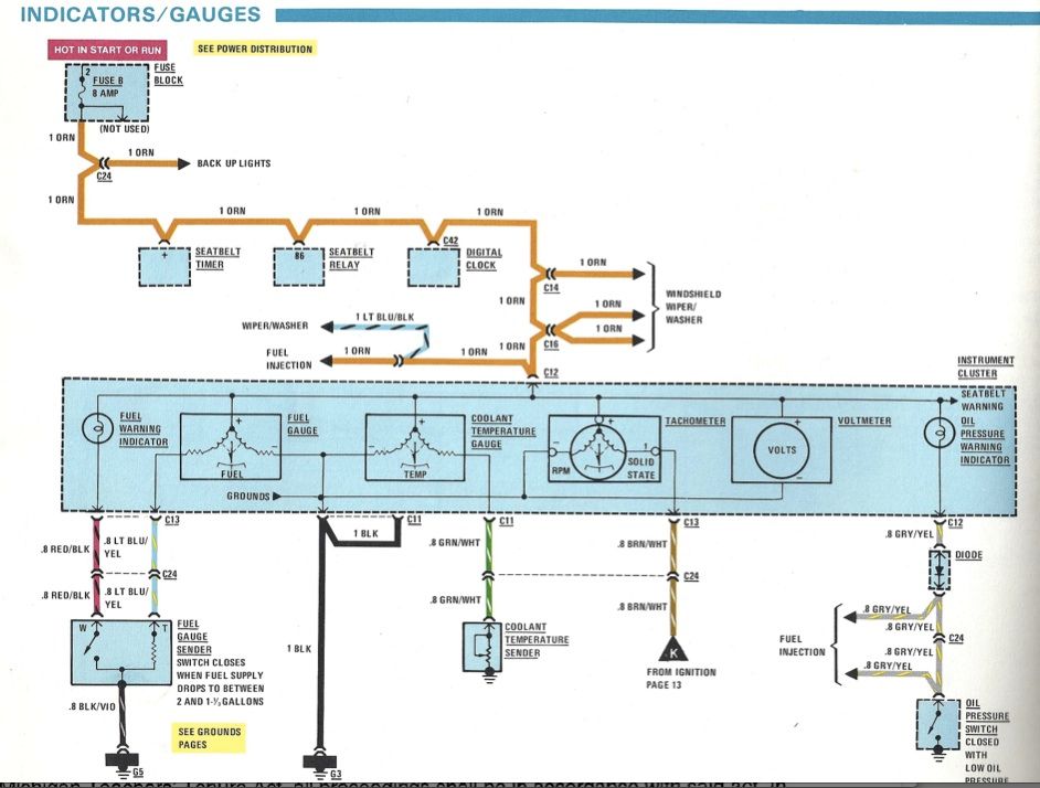
My recently bought X1/9 is not without its issues. My clock works but the main live feed is dead. All the fuses are correct and present.

Does anyone have a wiring diagram for this circuit?? I don't want to tap a live to this circuit without know why it stopped. My cigar lighter and interior lights also don't work. The Haynes book of lies manual covers all circuits except the one I want. Typical :)

Cheers.
 
Last edited:
I do...

x19clockpage1smbm1.jpg


x19clockpage2smai2.jpg


x19clockpage3sm.jpg


x19clockpage4smnp7.jpg
 
Thanks Bbrown butbinwas looking for where the live comes from. If I tap a wire into the feed from the ignition live the clock works. All fuses are correct but I've no idea where the love feed comes from or from what other circuit it feeds.
 
From the above, looks like an orange hot from seat belt relay powers the clock. This is from 80/81 though. YMMV.
clockcircuit_zps2ecaa51e.jpg
 
Cheers Jvandyke. I'll look into that. I think our UK cars were handcrafted very differently with less wiring than the US bound vehicles :) But this gives me an idea.
 
Also - check the inline fuses. My car has many. When I bought my car, the clock and interior light didn't work. I changed some inline fuses and both worked after that.
 
I managed to get the clock to work. One of the 2 inline fuses as mentioned within the electric cupboard just needed a little tweak.

Unfortunately I now seem to have lost a few warning lights, heater illuminator, fan and indicators. Roll on March when I get him out of hibernation for more investigation work. Other than thy though he's running like a dream.
 
here's a clock issue for you

Ever see one that spontaneously resets itself, as though someone pulled the battery? Sometimes twice a day, sometimes once a month. I'm guessing an internal issue and not a car power feed issue (dried out cap maybe).
 
Re-solder on the main board

The clock comes apart easily if you remove the front faceplate. There is a transistor with an aluminum tab on it. On the solder side of this component, it's likely you'll see slightly burnt solder connections. Re-solder carefully, as too much heat can (and will) damage the transistor regulator. FYI - This transistor is the main component of battery-sucking power to your clock. It's an old technology that supplies the 5VDC power to the clock chip.
 
all this clock talk has me thinking to go pull mine to convert to 12 hour, anything I can take inside to work on is a plus about now
 
Yes, if...

you're familiar with IC pinouts. As reference, the chip has a notch on one end that points to a tall tabbed transistor.
If you hold the chip so that the notch points forward, away from you, Pin 1 is on the notch-side left.
Pin 24 is on the notch-side right. Pin 12 is the bottom pin left, and Pin 13 is bottom pin right.
Pin's 11 and 12 are near the row of 4 small black transistors.
 
you're familiar with IC pinouts.

I'm hosed then…..

As reference, the chip has a notch on one end that points to a tall tabbed transistor.
If you hold the chip so that the notch points forward, away from you, Pin 1 is on the notch-side left.
Pin 24 is on the notch-side right. Pin 12 is the bottom pin left, and Pin 13 is bottom pin right.
Pin's 11 and 12 are near the row of 4 small black transistors.

maybe not!!! will give it a go
 
okay I think I've found the little buggers
clockgutstop_zps5ddb0873.jpg


clockgutsunder_zps9fb7ef4e.jpg


matches with this description too:

Art:
"5. Looking at the back side of the circuit board from front to rear (the front being the LED end the back being where the four wires leave the clock) you will see a row of solder connections where the LED clock face is connected at the front then a third of an inch (90mm) of mostly green space then a row of four large solder joints followed by a row of 14 smaller solder joints with short wires sticking out of them. These are the connecticng wires from the computer chip on the front of the circuit board. Using a sharp knife or screwdriver bend the two wires on the left side of the row of 14 together so that they touch. Once you get contact push on them firmly so they are up against each other and pressed against the green circuit board. This is what converts your clock to a 12 hour clock. Then reassemble your clock, plug it in (the plug only fits one way) and put it back in the dash by pushing it firmly in. Make sure you push the plug back far enough into the opening before inserting the clock so it leaves room for the clock to fit in."
 
Thanks

I see the heat sink in question in that picture you provided, but the transistor is shielded in the shot. Is it a small TO92 package or the larger TO220 or something else? Going to have to pop mine open this weekend and inspect.
 
I don't know. It's from an '81.
I bent those two pins close to eacher other and soldered them together, bench tested it and it works as a 12 hour, that didn't take long enough, now i have to go back out in the cold.
Here's another picture.
file_zpsb0cb216c.jpg
 
I see the heat sink in question in that picture you provided, but the transistor is shielded in the shot. Is it a small TO92 package or the larger TO220 or something else? Going to have to pop mine open this weekend and inspect.
Something else. It is an NSE180 in a TO202 package with an extra piece of aluminium riveted to the tab:

nse180.jpg


Forum member mqadry posted a schematic for the clock in this post.
 
Back
Top