I'm in the middle of the Brown Wire Mod on my '81X and can't figure out where to place the brown wire now that its run to the fuse box. I've read may posts and searched for current pictures but I cant seem to find any. Also there appears to be a number of off shoots of the mod I'm not sure what I should do or not do. My interior is completely ripped out so Its a blank canvas. So far I've done the following:
1. Upgraded the neg battery cable to 4ga.
2. Cleaned the ground connection on the firewall and inserted a new star washer, connected the
4 ga cable to the firewall (Star Washer against the firewall).
3. Purchased a multi connection positive battery terminal
4. Connected the starter cable and the original brown wire plus the red wire to the new terminal
5. Ran the new 10ga brown wire in tandem with the original brown wire through the firewall grommet and connected it to the new multi connector battery terminal.
So where I'm at a standstill is:
1. I don't know how to connect the new brown wire to the fuse box. My '81 has no open terminal to connect to.
2. How can I upgrade these connections for future mods such as headlight, wiper and power window mods? I have everything open and now is the time to do it but I'm an electrical neophyte and need screen shots to help me along.
3. I don't understand how relays function, or where to place fuses and why certain ga. wires are necessary for certain situations so I need guidance.
Again I've been reading all the posts on the subject and I can't find one that I can be confident in that I'm doing the right thing.
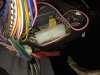
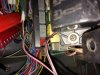
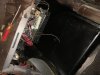
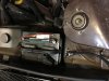
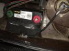
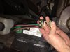
Pics of my progress:
I would install another bus bar on the firewall like this one:
This has been done by others and gives you multiple places to pull power from.
In regards to where to attach your additional brown wire, I believe you need to attach to one of the existing wires on that existing block. Others have made a mechanical connection to connect all of the wires to each other. This would omit the existing block you have in your pictures.
A relay is a switching device which in it's simplest form would have four connections. A relay uses a low current to actuate a switch to a higher current load. So instead of providing enough current through the column switch to activate the starter you install a relay which places a very small load on the column switch to actuate a contact that supplies power to the solenoid from a reliable source in the engine bay. The relay should have a schematic molded or printed on the case. Basic diagram will show a curly line, the pick up coil or control power. And two other points connected by what looks like a little draw bridge. That is where you attach the higher power supply and power to starter wires.
This is a Ford style external start solenoid... The two little lugs on the front control the switch and the two larger side lugs are used to provide high power to the starter. This dramatically reduces the amount of current required to flow through your column switch thereby reducing heat and extending switch life.
I hope this didn't come off to simplistic but that is a general overview of what you are trying to do with these mods. Move multiple high current loads off control switches to their own circuits so they work more effectively without competing against each other for power from a single conductor.
Regards
Going back to your original question. If there isn't an open lug to attach your new brown wire to, the intent is that you would attach it to the existing brown wire near the point where it attaches to the fuse box.
5. Find the LARGE BROWN WIRE and at a convenient spot on EITHER side of the connector... strip back about 1/2 inch of insulation and tie the new 10 guage wire to it... wrapping it around securely (a T splice) and preferably soldering it. Cover with electrical tape, inspect the connector and clean, replace and button up the cover.
The other part of the brown wire mod is running an additional 10ga wire to the brown wire that feeds the ignition switch, the installation is very much the same as at the fuse box: On the "hot" (always on) brown wire leading to the ignition switch tie your new brown wire to the wire by stripping it back and soldering the new wire to the old wire.
As an addition to the above statements by Rocco, many use multiple relays to provide clean power to secondary circuits from the bus bar and additional fuses. Examples include wipers (two relays to run the two speeds), head lights (high beam and low beam), a starter relay (using a relay to engage the solenoid which takes the load off the ignition switch) and some will use a large relay like the Ford one above as a load reduction relay which shuts off power to many accessories while the starting sequence ongoing.
A quick search will bring you to multiple threads which delineate how to do many of these things. Some of the relay sets can be bought, the starter relay for example can be bought here:
https://sites.google.com/site/vanagonheadlightrelays/hard-start-relays/hard-start-relay
This is a real quality piece (they have an even better one for 7 dollars more that is water proof), it can be mounted in the spare tire well. This relay set up is very easy to make yourself and given that it is located inside the vehicle you can use a low cost relay and connectors.
All of the relay setups can be built by you with some simple tools and a selection of wire, connectors and relays. Hope that helps.
The existing references (shared by Karl above) should provide most of what you need. In addition, here's the approach I followed on my 81x.
1. I "bolted" two 10ga wires to the existing 12v factory connection since I didn't want to cut or modify it. You can see some of it in the pic below.
2. Both of the wires were squeezed thru the exisiting firewall grommet. Tight but worked ok.
3. I attached one wire to the 4-way connector in the fuse/relay area (already documented in the links above)
4. I attached the other wire to an auxiliary fuse panel that I use to power remote relays for headlights, wipers, subwoofer, etc.
I mounted the aux fuse panel in the passenger footwell area just high enough on the firewall that nobody will kick it
But low enough that I can get to it...
Hope this helps!
Hello dailydriver,
I have just finished the BWM running two parallel 10g brown wires and a second 10g pink or in my case black wire to the fuse block. All from a distribution bar in the footwell. Posted schematics on the XWeb of what I did based on all the wonderful information on the XWeb.
I have also posted videos of my work on YouTube. Type in "FIAT X1 9 Brown Wire Mod" or "FIAT X1 9 Headlight Mod" and that will get you to my vids. Channel name is Craig Sheppard. Hope it helps in someway.
This site uses cookies to help personalise content, tailor your experience and to keep you logged in if you register.
By continuing to use this site, you are consenting to our use of cookies.


")

