
Pete Whitstone
True Classic
To get the tech side of the Scorpion forum rolling, I thought I'd post a write-up of how I installed my Euro bumpers.
When the bumpers arrived, they were sanded on the gel-coated side but were raw fiberglass on the back side. This was good because I was going to be glassing in the mounting brackets, and needed an unfinished fiberglass surface for the new glass to adhere to.
The front installation:
First up is removal of the front bumper, the under-bumper valence, and the bumper shocks. Here is a shot of the car after this was complete.
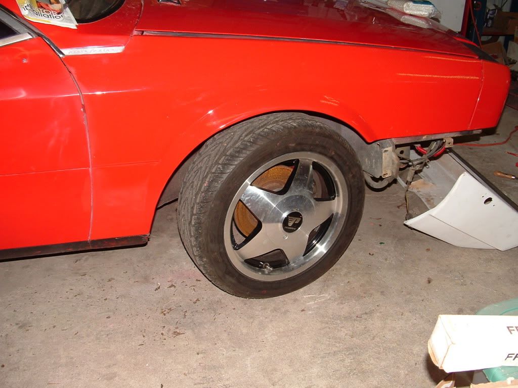
In this shot you can see the stock mounting brackets for the under-bumper valance – one in the wheel well with 2 vertical mounting holes, and the small angle about 8 inches forward of that. The new bumper would need to attach to those mounting points.
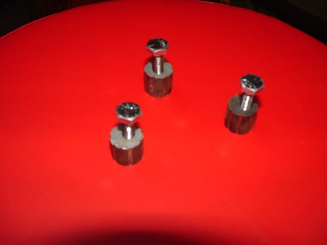
My plan for that was to glass some mounting points for screws into the front bumper, at the 3 points that the stock under-bumper valence mounts. I started with some 5/8” solid round stock, and cut some slits along its length to give the new glass something to grab onto. I then cut them into half-inch lengths, and drilled and tapped a mounting hole for the screw. Here is what they looked like when done.
Then I glassed them into the sides of the front bumper in 3 different sessions, using multiple strips of glass mat in each session to spread the load out. Here is a shot from during that operation.
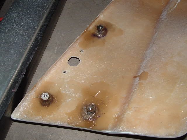
In that shot you can see the holes I cut out for mounting the side lights. They are in roughly the same location as stock.
These 6 (3 on each side) mounting points secure the bumper, but the weight of the bumper rested on the top lip of it, just below the headlights. There is a “shelf” on the Scorpion that this sits on, but it was just a hair low for mounting my bumper, so I raised it a bit by adding a strip of aluminum flat bar which I J-B welded in place. It is visible just under the AC condenser in this shot:
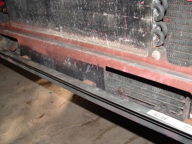
Also visible is a piece of angle I mounted to the front of the car, using 4 studs that were used to mount the old under-bumper valence. You can see that I spaced it off the car slightly with some small pieces of square tube. I later decided to switch this to a stack of washers. I slotted the 4 mounting bolt holes horizontally, so I could adjust it up and down slightly. I could also space it further in or out by subtracting or adding washers. This piece of angle would provide a second bearing point for the weight of the bumper, which was not on the edge of the top lip. I’m not altogether sure this was necessary, but I tend to over-engineer, so there it is.
On the bumper side, I glassed in another piece of angle, that would sit on top of the one described above, and bear some of the weight of the bumper. (I should note here that the bumper was not at all heavy, it was probably only a few lbs as delivered, and was certainly less then 7 lbs installed.) Here are some shots of the piece of angle I glassed into the bumper.
In the first shot you can see the hole that was cut out for the small grill under the bumper in the center of the car. In the second shot you can see the holes that were cut out for the blinker (on the left) and for more airflow through the radiator (on the right – more on that later).
Back to the side mounting points. There are two original brackets, the first is a small 90-degree piece that is bolted to the body from the washer bag/motor compartment on the drivers side and the battery compartment on the passenger side. This bolts to the single, more forward mounting point. I was able to re-use the stock bracket here, with some minor bending and slotting.
On the more rearward bracket that mounts in the wheel well, my original plan was to re-use the stock brackets. But I quickly realized that I had not been precise enough in my measurements of the glassed-in mounting points I had created. I would have to create my own brackets that would allow some degree of adjustability. I did this out a piece of aluminum flat and a piece of aluminum angle. Here is a shot of that bracket.
The slot on the flat provides for in/out adjustment, and the angle at the top of the “T” can be changed as well.
Once everything was test-fitted and I was satisfied with the mounting position, it was time for paint. I primed with PPG DP-48 and some flexibilizer, and then shot the single-stage finish coat. Here is a shot of the front bumper right after the finish coat was applied.
If you look close, you can see the T-bracket is mounted in place.
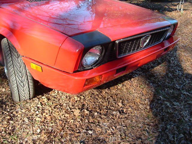
The final step before mounting the bumper was mounting the blinkers and grills. The lower grill hole was filled with the stock grill, but the two new air-cooling holes (in what I presume is the fog-light location) needed some grill material. I went to the local hardware store and got some “expanded metal” that’s used for barbeque grills, and cut, primed, painted, and glassed it in. To mount the blinkers, I just bent some aluminum C-channel, drilled a hole in it, and used the studs on the blinkers to mount it. This is all visible in this shot.
And finally, here is a shot of the finished product.
The rear installation:
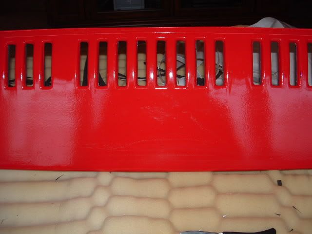
The first order of business on the rear bumper was cutting out all the small vertical slots that are immediately behind the exhaust. I did the long side of the slots with a die grinder and cut-off wheel, then drilled a large hole at the top and bottom. This removed enough meat that I was able to snap out the remaining piece. Then I spent some time with a flat file and a rat-tail file and smoothed each hole to a uniform size and shape.
Then I removed the stock rear bumper, the under-bumper valance, and the bumper shocks. Once this was complete, I began looking for a way to mount the rear bumper. Like the front bumper, this turned out to be a two-part process. First, I needed something to bear the weight of the bumper, and second, I needed some mounting points on the sides of the bumper to hold everything in place.
The stock under-bumper valance has two mounting brackets underneath the bumper shock mounting point, and I used these “tabs” to bear the weight. This was done two ways. First, I welded up a piece of angle and some round tubing, which sat on top of the stock under bumper valance mounting points. This is shown in these shots.
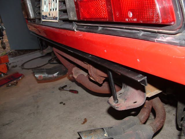
The angle runs just under the stock bodywork and for almost the entire length of the car. The fiberglass bumper upper lip sits on this. To attach it to the car, I welded a nut onto the bottom of the round tube, and then ran a bolt up from underneath, through the tab, into the welded-on nut, and finally up into the hollow tube. You can bend the tabs around slightly to change the height or forward/rearward angle of the whole arrangement.
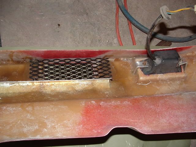
I also glassed into the bumper a small piece of angle that would rest on the tabs, so the weight of the bumper is actually supported at three points. This small piece of angle is visible in this shot.
The V is cut in it to sit around the vertical upright tube that was now sitting on the tab. Also visible in this shot is a piece of angle that I glassed into each side of the bumper. When the bumper is mounted in place, this sits immediately behind the sheet metal in the rear of the wheel well. Two screws were run through that sheet metal and into these pieces to help hold the bumper in place.
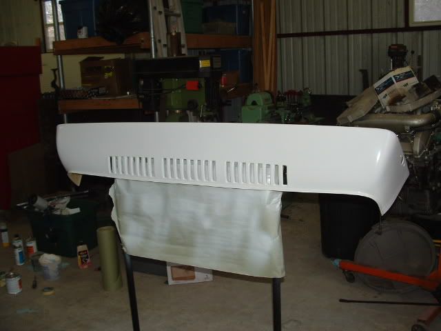
Then it was on to paint. Here is a shot of the rear bumper after primer but before topcoat.
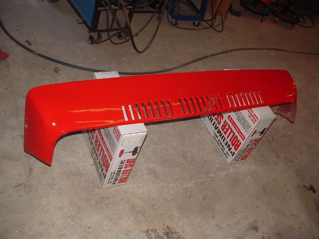
And here it is after the finish coat has been applied.
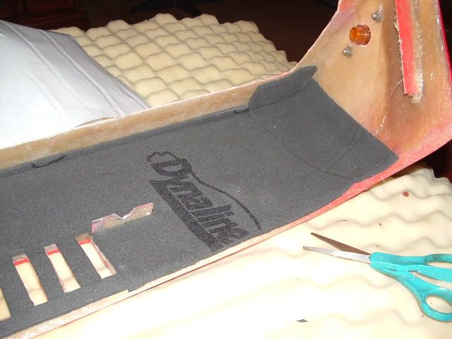
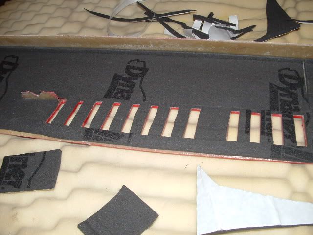
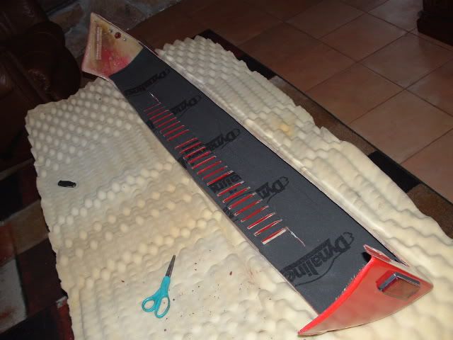
Finally, there were two pads on the sides of the rear bumper at the top, that were also intended as mounting points. Bolts drop down from the bodywork into these. The bolts are located in the engine compartment near the taillights. The drivers side is fairly open, but on the passenger side you will have to remove the coolant tank for access. I used a large rubber grommet on the bolt between the body and the bumper. Once I was satisfied with all the fit & finish, the last step was to apply some heat insulation, to protect the rear bumper from the heat of the exhaust. I used 1/8” Dynamat, here are some shots of the installation.
It’s not visible from the outside, and is cheap insurance against warping or peeling paint, in my opinion.
All in all, the rear was quite a bit simpler than the front.
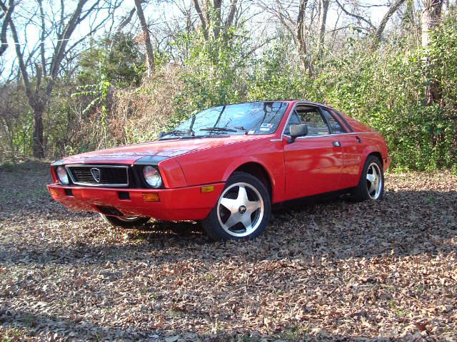
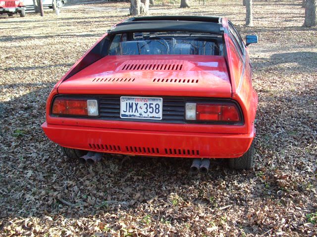
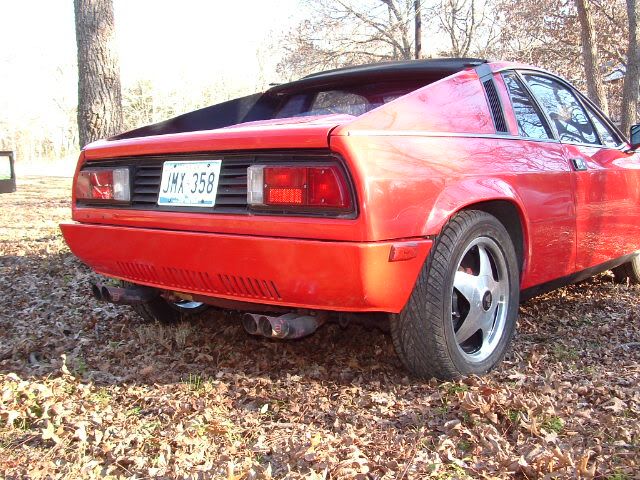
Here are some shots of the finished car. Enjoy!
When the bumpers arrived, they were sanded on the gel-coated side but were raw fiberglass on the back side. This was good because I was going to be glassing in the mounting brackets, and needed an unfinished fiberglass surface for the new glass to adhere to.
The front installation:
First up is removal of the front bumper, the under-bumper valence, and the bumper shocks. Here is a shot of the car after this was complete.
In this shot you can see the stock mounting brackets for the under-bumper valance – one in the wheel well with 2 vertical mounting holes, and the small angle about 8 inches forward of that. The new bumper would need to attach to those mounting points.
My plan for that was to glass some mounting points for screws into the front bumper, at the 3 points that the stock under-bumper valence mounts. I started with some 5/8” solid round stock, and cut some slits along its length to give the new glass something to grab onto. I then cut them into half-inch lengths, and drilled and tapped a mounting hole for the screw. Here is what they looked like when done.
Then I glassed them into the sides of the front bumper in 3 different sessions, using multiple strips of glass mat in each session to spread the load out. Here is a shot from during that operation.
In that shot you can see the holes I cut out for mounting the side lights. They are in roughly the same location as stock.
These 6 (3 on each side) mounting points secure the bumper, but the weight of the bumper rested on the top lip of it, just below the headlights. There is a “shelf” on the Scorpion that this sits on, but it was just a hair low for mounting my bumper, so I raised it a bit by adding a strip of aluminum flat bar which I J-B welded in place. It is visible just under the AC condenser in this shot:
Also visible is a piece of angle I mounted to the front of the car, using 4 studs that were used to mount the old under-bumper valence. You can see that I spaced it off the car slightly with some small pieces of square tube. I later decided to switch this to a stack of washers. I slotted the 4 mounting bolt holes horizontally, so I could adjust it up and down slightly. I could also space it further in or out by subtracting or adding washers. This piece of angle would provide a second bearing point for the weight of the bumper, which was not on the edge of the top lip. I’m not altogether sure this was necessary, but I tend to over-engineer, so there it is.
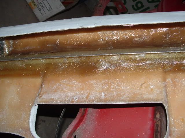
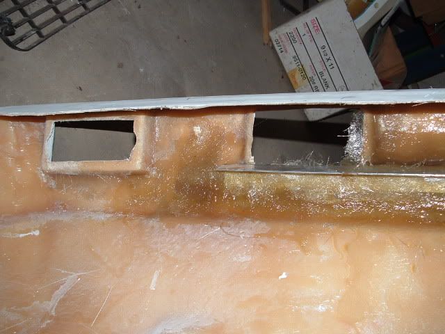
On the bumper side, I glassed in another piece of angle, that would sit on top of the one described above, and bear some of the weight of the bumper. (I should note here that the bumper was not at all heavy, it was probably only a few lbs as delivered, and was certainly less then 7 lbs installed.) Here are some shots of the piece of angle I glassed into the bumper.
In the first shot you can see the hole that was cut out for the small grill under the bumper in the center of the car. In the second shot you can see the holes that were cut out for the blinker (on the left) and for more airflow through the radiator (on the right – more on that later).
Back to the side mounting points. There are two original brackets, the first is a small 90-degree piece that is bolted to the body from the washer bag/motor compartment on the drivers side and the battery compartment on the passenger side. This bolts to the single, more forward mounting point. I was able to re-use the stock bracket here, with some minor bending and slotting.
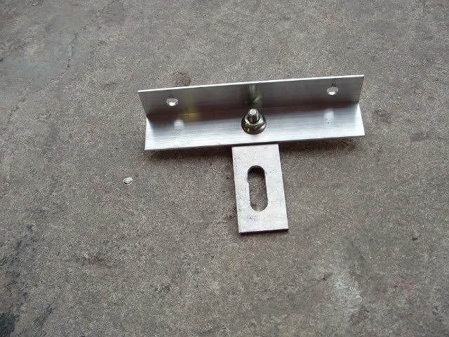
On the more rearward bracket that mounts in the wheel well, my original plan was to re-use the stock brackets. But I quickly realized that I had not been precise enough in my measurements of the glassed-in mounting points I had created. I would have to create my own brackets that would allow some degree of adjustability. I did this out a piece of aluminum flat and a piece of aluminum angle. Here is a shot of that bracket.
The slot on the flat provides for in/out adjustment, and the angle at the top of the “T” can be changed as well.
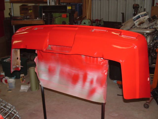
Once everything was test-fitted and I was satisfied with the mounting position, it was time for paint. I primed with PPG DP-48 and some flexibilizer, and then shot the single-stage finish coat. Here is a shot of the front bumper right after the finish coat was applied.
If you look close, you can see the T-bracket is mounted in place.
The final step before mounting the bumper was mounting the blinkers and grills. The lower grill hole was filled with the stock grill, but the two new air-cooling holes (in what I presume is the fog-light location) needed some grill material. I went to the local hardware store and got some “expanded metal” that’s used for barbeque grills, and cut, primed, painted, and glassed it in. To mount the blinkers, I just bent some aluminum C-channel, drilled a hole in it, and used the studs on the blinkers to mount it. This is all visible in this shot.
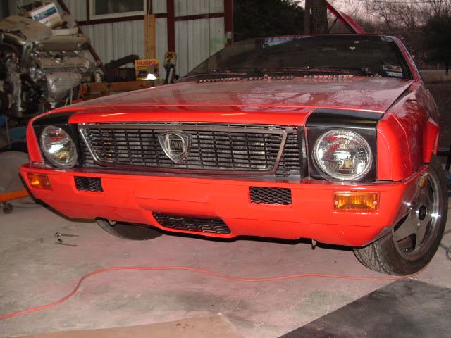
And finally, here is a shot of the finished product.
The rear installation:
The first order of business on the rear bumper was cutting out all the small vertical slots that are immediately behind the exhaust. I did the long side of the slots with a die grinder and cut-off wheel, then drilled a large hole at the top and bottom. This removed enough meat that I was able to snap out the remaining piece. Then I spent some time with a flat file and a rat-tail file and smoothed each hole to a uniform size and shape.
Then I removed the stock rear bumper, the under-bumper valance, and the bumper shocks. Once this was complete, I began looking for a way to mount the rear bumper. Like the front bumper, this turned out to be a two-part process. First, I needed something to bear the weight of the bumper, and second, I needed some mounting points on the sides of the bumper to hold everything in place.
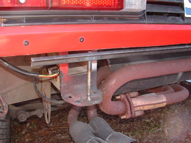
The stock under-bumper valance has two mounting brackets underneath the bumper shock mounting point, and I used these “tabs” to bear the weight. This was done two ways. First, I welded up a piece of angle and some round tubing, which sat on top of the stock under bumper valance mounting points. This is shown in these shots.
The angle runs just under the stock bodywork and for almost the entire length of the car. The fiberglass bumper upper lip sits on this. To attach it to the car, I welded a nut onto the bottom of the round tube, and then ran a bolt up from underneath, through the tab, into the welded-on nut, and finally up into the hollow tube. You can bend the tabs around slightly to change the height or forward/rearward angle of the whole arrangement.
I also glassed into the bumper a small piece of angle that would rest on the tabs, so the weight of the bumper is actually supported at three points. This small piece of angle is visible in this shot.
The V is cut in it to sit around the vertical upright tube that was now sitting on the tab. Also visible in this shot is a piece of angle that I glassed into each side of the bumper. When the bumper is mounted in place, this sits immediately behind the sheet metal in the rear of the wheel well. Two screws were run through that sheet metal and into these pieces to help hold the bumper in place.
Then it was on to paint. Here is a shot of the rear bumper after primer but before topcoat.
And here it is after the finish coat has been applied.
Finally, there were two pads on the sides of the rear bumper at the top, that were also intended as mounting points. Bolts drop down from the bodywork into these. The bolts are located in the engine compartment near the taillights. The drivers side is fairly open, but on the passenger side you will have to remove the coolant tank for access. I used a large rubber grommet on the bolt between the body and the bumper. Once I was satisfied with all the fit & finish, the last step was to apply some heat insulation, to protect the rear bumper from the heat of the exhaust. I used 1/8” Dynamat, here are some shots of the installation.
It’s not visible from the outside, and is cheap insurance against warping or peeling paint, in my opinion.
All in all, the rear was quite a bit simpler than the front.
Here are some shots of the finished car. Enjoy!