Dan Sarandrea (Phila)
Waitin' On Parts...
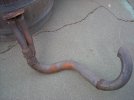
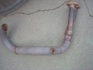
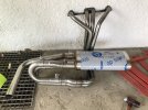
Wow that's one sexy header!!!!I deleted the catalytic converter and installed this header (made in UK). I has no provision for an O2 sensor. Do I need to provide one? My X is 1980 with Fuel Injection and performance head by MWB. It started fine yesterday and seems to idle smoothly.View attachment 61244
The problem with headers on FI cars is that most of the time there is no factory-equivalent place for the oxy sensor. Put it down past the collector where the 2 pipes join into 1 and it might be too far away to stay hot (early oxy sensors are not heated like todays are). Put it closer to the source and now you're only reading one hole and not all four.
OTOH on our cars the oxy sensor doesn't have a huge impact like they do on todays cars, so I guess it all comes out in the wash
")