
Dan Sarandrea (Phila)
Waitin' On Parts...
I had intentions of implementing Bob Brown's patented and improved Brown Wire Mod, but when I got into it, the hard part was getting the addditional wire to seat nicely in the four-prong junction fitted to the front edge of the later cars ('84 and up) ATC fuse box. Not to mention that these are push on spade connectors which aren't the greatest for connectivity in the first place.
And I wanted to implement the Bob Brown no-cut headlight relay mod as well as the Leiszig wiper relay mod, too. But no matter what I did, I ended up with unsightly wires coming off the battery postive post and a mishmash of inline fuses.
So I decided to over-engineer and over-build a replacement power distribution system.")
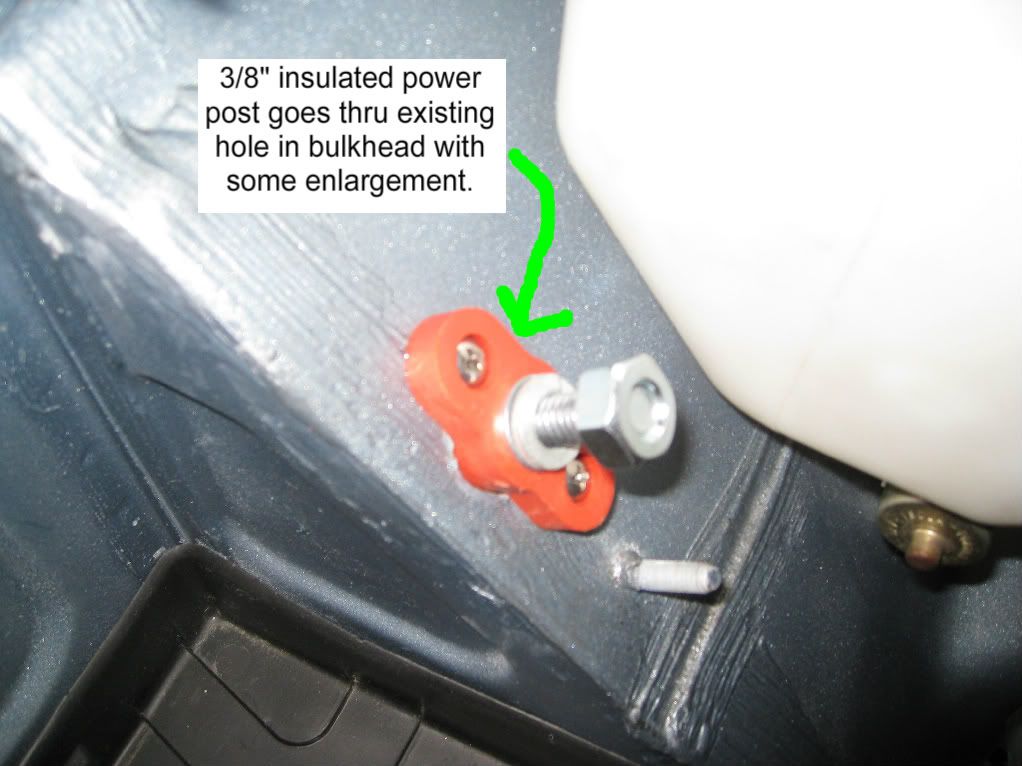
First, fit a thru-the-bulkhead insulated power post thu the existing cable hole. The good news is that this fits nicely under the stock battery cover.
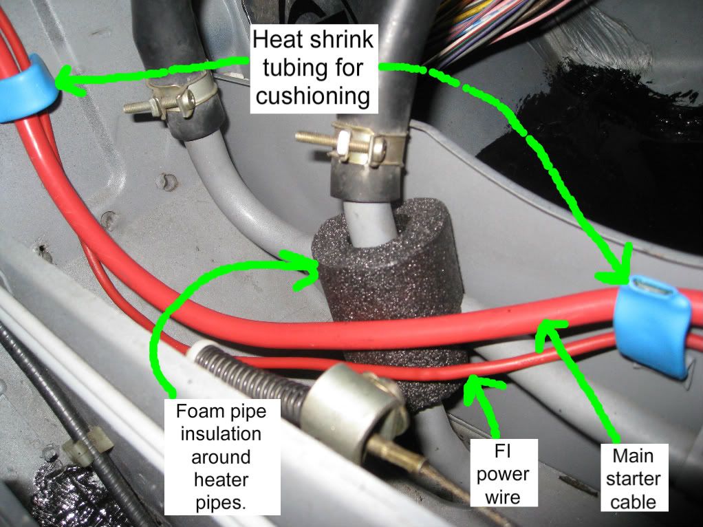
Then fab up a replacement starter/main power cable, adding two wire sizes for good measure (from #4 to #0). Fit said starter cable to the inside of the insulated power post. Since the FI power wire runs along with the main cable, make up a #10 replacement. Careful routing around the heater pipes.
Now that I have an interior power post, I was able to use this as the jumping off point to feed the wiper relays and the headlight relays.
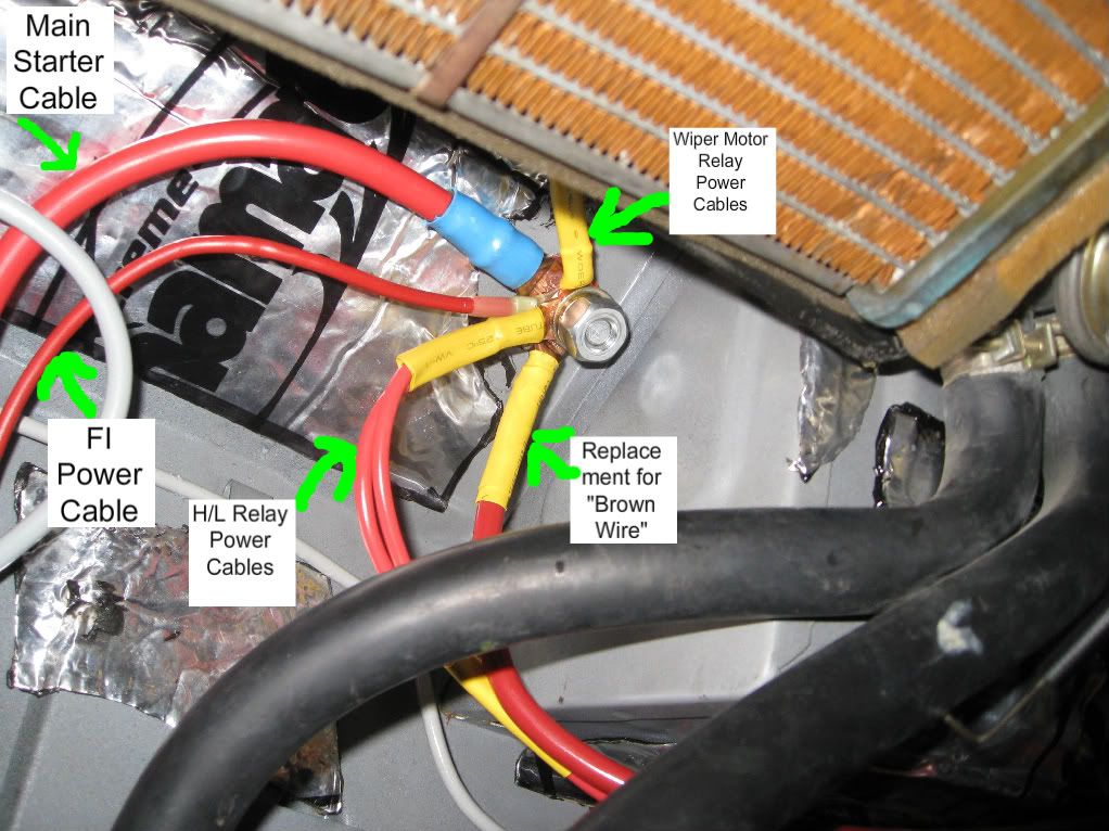
I executed my interpretation of the brown wire mod by running a branch from the main power post to a surface mounted power post located just behind the ATC fuse box. I used #6 wire with copper lugs.
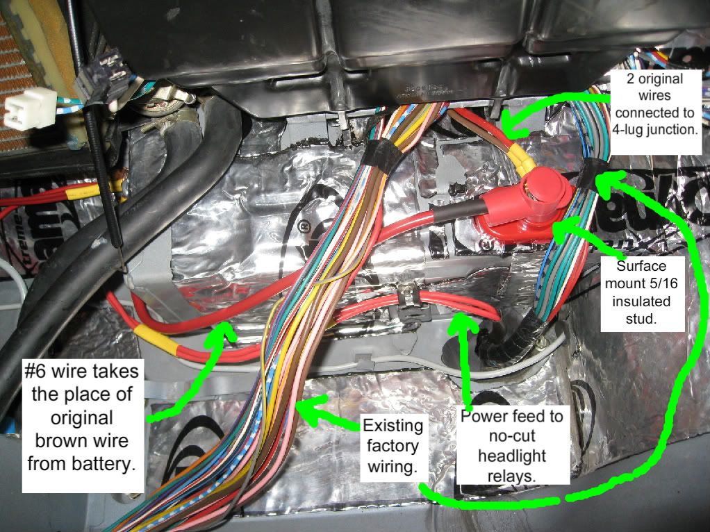
The two smaller wires called out in the pic above are the two original wires that occupy two of the four male spades that live in the original power junction receptacle originally located at the front of the ATC fusebox. Replaced their female spade connectors with copper rings. The third wire, the original brown wire that comes from the battery, is replaced by the #6 branch.
I will be posting three more threads in the near future with pix of how I did the wiper relays, the headlight relays, the hard start relay and an upsize of the main alternator/charging wire.
And I wanted to implement the Bob Brown no-cut headlight relay mod as well as the Leiszig wiper relay mod, too. But no matter what I did, I ended up with unsightly wires coming off the battery postive post and a mishmash of inline fuses.
So I decided to over-engineer and over-build a replacement power distribution system.
First, fit a thru-the-bulkhead insulated power post thu the existing cable hole. The good news is that this fits nicely under the stock battery cover.
Then fab up a replacement starter/main power cable, adding two wire sizes for good measure (from #4 to #0). Fit said starter cable to the inside of the insulated power post. Since the FI power wire runs along with the main cable, make up a #10 replacement. Careful routing around the heater pipes.
Now that I have an interior power post, I was able to use this as the jumping off point to feed the wiper relays and the headlight relays.
I executed my interpretation of the brown wire mod by running a branch from the main power post to a surface mounted power post located just behind the ATC fuse box. I used #6 wire with copper lugs.
The two smaller wires called out in the pic above are the two original wires that occupy two of the four male spades that live in the original power junction receptacle originally located at the front of the ATC fusebox. Replaced their female spade connectors with copper rings. The third wire, the original brown wire that comes from the battery, is replaced by the #6 branch.
I will be posting three more threads in the near future with pix of how I did the wiper relays, the headlight relays, the hard start relay and an upsize of the main alternator/charging wire.
Last edited: