LoveX1/9s
True Classic
I wanted to replace the sensor but it’s complicated. I wanted 2 fans and I had them all along but the sensor that is supposed to do the trick will not.
All indications are that the sensor is shot so the car will not start when hot (not saying that there aren’t other things and I have already fixed one).
The car starts when the gas pedal is depressed to the floor without pumping and turning the key. So, my air fuel ratio is off – faulty sensor, right???
I am no mechanic but I am becoming one – sort of.
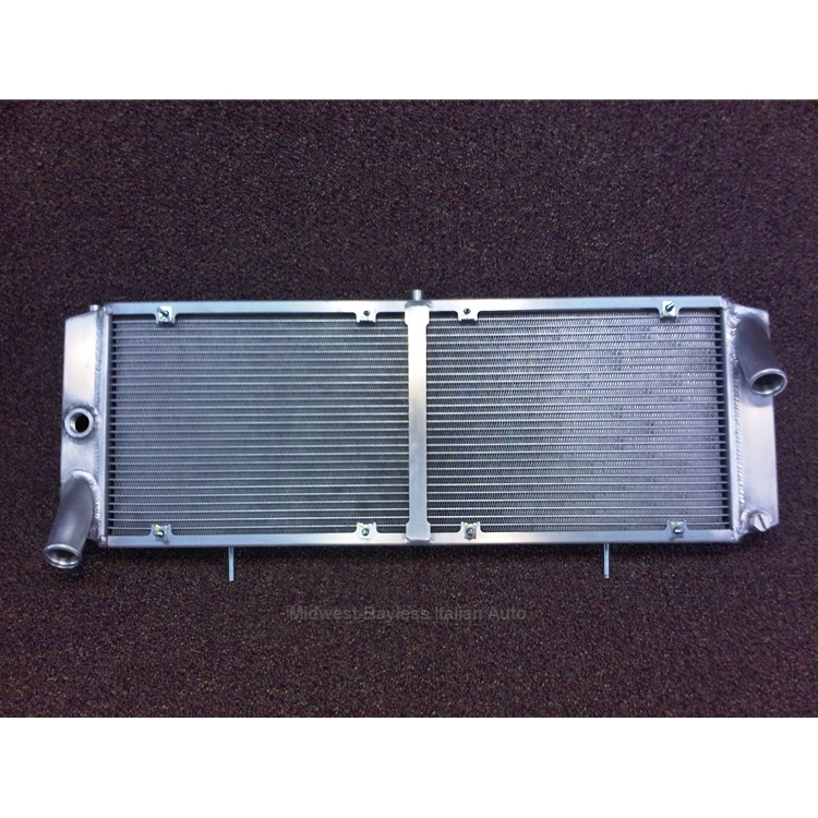
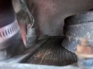
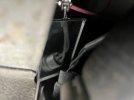
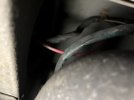
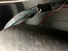
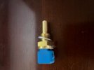
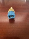
As you can see, the sensor on the car is not the same as the one that’s supposed to replace it. I don’t know if I have 2 fans because I have air conditioning or if the radiator is aftermarket but what do I need to do to complete a simple job (Yes, the fuse is good)?
That said am I confusing the part with the Radiator Cooling Fan Switch??? I'm not a mechanic remember??? One repair book say's the sensor is on the back of the reaiator on the drivers side. Will doubble check with the shop manual too. BTW, isn't the sensor on the block some where on most cars??? Yes, I'm confused ;-)
This post is related to another post – Car will not start when warm.
All indications are that the sensor is shot so the car will not start when hot (not saying that there aren’t other things and I have already fixed one).
The car starts when the gas pedal is depressed to the floor without pumping and turning the key. So, my air fuel ratio is off – faulty sensor, right???
I am no mechanic but I am becoming one – sort of.
As you can see, the sensor on the car is not the same as the one that’s supposed to replace it. I don’t know if I have 2 fans because I have air conditioning or if the radiator is aftermarket but what do I need to do to complete a simple job (Yes, the fuse is good)?
That said am I confusing the part with the Radiator Cooling Fan Switch??? I'm not a mechanic remember??? One repair book say's the sensor is on the back of the reaiator on the drivers side. Will doubble check with the shop manual too. BTW, isn't the sensor on the block some where on most cars??? Yes, I'm confused ;-)
This post is related to another post – Car will not start when warm.
Attachments
Last edited: