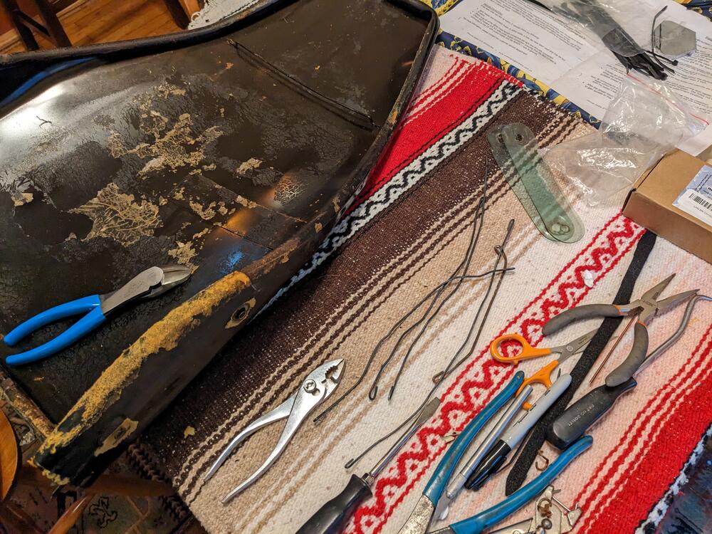
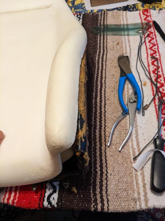
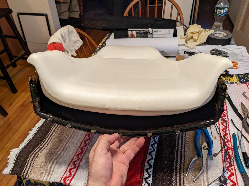
The hairpin spring keeps the rocker in contact with the ball end. Neat.
I found this on zcar.com in a post by Kevin Taylor

www.zcar.com
This is a general instruction of "How To adjust Valves on a L-Series Engine" with a stock camshaft.
Note the following :
****************CAUTION*********** CAUTION *********CAUTION *******************
WHILE THE CAM COVER IS OFF, BE AWARE OF LOOSE OR FOREIGN OBJECTS IN YOUR WORK AREA THAT CAN POTENTIALLY FALL INTO THE OPEN ENGINE, SPECIFICALLY THE AREA FORWARD OF THE TIMING CHAIN.
*******************************************************************************
You'll need some basic hand tools:
* Screwdriver - Phillips
* 10 MM 1/4 Dr. socket w/ long extention
* Feeler gauges (.008", .010" and .012")
* Open-end Wrenches (14 MM & 17 MM),
* 27 MM socket on a breaker bar or a remote starter switch
* Torque wrench, 25-100 Ft pound range, minimum .
* 3/8 or 1/2 Dr 17 MM Crowsfoot or 1/2 Dr L28 Vlv Adj Tool from MSA.
You'll perform the adjustment twice, once while the engine is bone cold (basically for the sake of practice and to gain a feel for it) and again while the engine is hot and at operating temperature to finalize the adjustments.
Orientate yourself with the engine, such as the firing order and cylinder arrangement. Firing order is 1-5-3-6-2-4, cylinders are numbered from front to back. Cylinders 1 & 6 will mirror each other but are 180 degrees out. Each cylinder is seperated by 60 degrees of crankshaft rotation.
Obtain and organize noted tools
***** Cold Adjustment *****
1.0) Gain Access
Open hood to gain access to cam cover. Dis-connect breather hose from elbow fitting common to the cam cover. Loosen all attach bolts (10 plcs) and remove fasteners. Pop cam cover free from cylinder head, remove cam cover and gasket, set aside to avoid contamination. Wipe excess oil from surfaces as required
*
2.0) Adjust #1 Cylinder
Rotate the Engine until the #1 Cylinder is @ TDC on the compression stroke.
*NOTE: This will be evident when both cam lobes are pointed upward at approximately the 11:00 & 1:00 O'Clock positions.
2.1) Measure Valve clearance
Insert the applicable feeler gauges in between the intake & exhaust cam lobes (.008" and .010" respectively) and the associated rocker arm from driver's side of the cam. Make note of the runners on the opposite side of the head to determine if it is a intake or exhaust. Check for slip fit at each Rocker arm.
** NOTE: On rocker arms with insufficient clearance (too tight valve clearance), it may be necessary to slaken the 17 MM locknut to obtain sufficient clearance it insert the feeler.
2.2) #1 Exhaust valve .010"
The #1 cylinder exhaust valve is the most forward cam lobe closest to the radiator. Loosen 17 MM locknut while holding Rocker Arm Pivot with a 14 MM open-end. Rotate pivot with 14 MM wrench until a slip fit with the .010" feeler gauge is obtained. Tighten 17 MM locknut to 40 Ft Lbs while holding Rocker Arm Pivot from moving. Re-check valve lash after tightening, as settings will have a tendency to close due to the stretching of the Pivot during tightening. Repeat adjustment as necessary until a slip fit of the feeler gauge is obtained
2.3) # 1 Cylinder Intake .008"
The #1 cylinder Intake valve is set to .008" Loosen 17 MM locknut while holding Rocker Arm Pivot with a 14 MM open-end. Rotate pivot with 14 MM wrench until a slip fit with the .008" feeler gauge is obtained. Tighten 17 MM locknut to 40 Ft Lbs while holding Rocker Arm Pivot from moving. Re-check valve lash after tightening, as settings will have a tendency to close due to the stretching of the Pivot during tightening. Repeat adjustment as necessary until a slip fit of the feeler gauge is obtained.
*
3.0) Adjust remaining Cylinders
Rotate Engine 60 degrees CW until the #5 Cylinder is @ TDC. Repeat steps 2.1 through 2.3 for the #5 Cylinder. Repeat the process until all cylinders have had both valve clearances adjusted per steps 2.1 through 2.3.
*
4.0) Re-assemble Engine
Re-assemble cam cover to cylinder head, noting the following:
4.1) Mouse trap springs are all secured in place, All pivot locknuts torqued OK, engine top end is FOD free, no tools or feelers left behind.
4.2) Cam Cover Gasket mating surfaces are clean and oil free. Gasket is in a good servicable condition. OEM Nissan gasket is re-usable if not torn or excessively worn.
4.3) Insert Cam Cover bolts to pick-up Gasket, use tabs on gasket to reposition gasket. Once all fasteners are installed, run bolts down buy hand with the 10 MM socket & extension just until the heads are seated.
4.4) Starting from the center, tighten Cam Cover bolts to 25 inch-Lbs followed by the opposing fastener on the opposite side, alternating front to back while tightening bolts. Repeat sequence until all fasteners are snug.
** NOTE: * * * * WARNING * * * *
DO NOT OVER TIGHTEN CAM COVER BOLTS, STRPPING OF THREADS IN CYLINDER HEAD MAY OCCUR.
4.5) Re-connect breather hose to Cam Cover elbow, tightening clamp as required.
*
5.0) ***** Hot Adjustment ******
Adjust clearances as quickly as possible due to the cooling affect on the engine. The cold Adjust is done as a preliminary and the Hot adjust is final tweekage if and as required. Some valves may or may not need further action.
Start engine, heat soak the engine up to optimum operating temperature. Repeat adjustment steps 1.0 through 3.0 except as noted:
*NOTE: Hot Adjustment is the same as Cold Adjustment, except the valve clearances have increased approximately .002", thus the Hot Adjust is performed using the following feeler gauge sizes.
Hot Adjust Feeler gauge sizing: Intake = .010"/ Exhaust = .012"
5.1) Re-assemble engine to a normal servicable condition. Re-install Cam Cover as required.
6.0) Repeat Valve Adjustment every 30,000 miles or every tenth oil change.
Enjoy the ride


