1603cc engine build

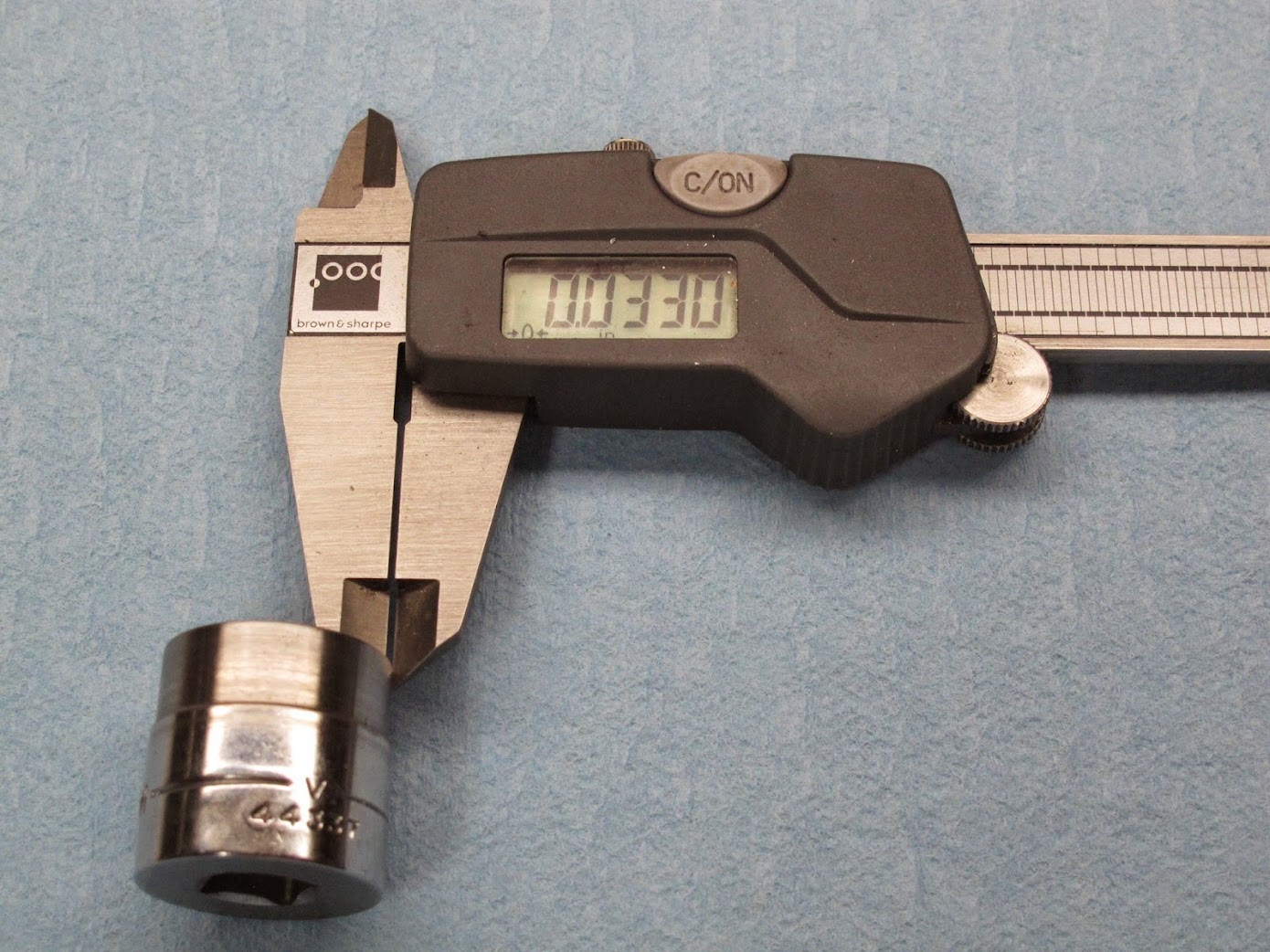
Extra thin wall socket is not a limitation.

This is a absolutely nothing special 3/8" drive 3/4" Sears Craftsman socket that was modified on a lathe with a min wall thickness of 0.033" and it has installed and removed (with red loctite, heated to break the bond, about 100 ft/lb) these ARP flywheel cap screws many times with zero problems.
3%3A4%22%2Bsocket%2C%2B0.033%22%2Bwall.JPG


Here is a Snap-On SESU spline drive flex socket designed for high torque, high strength spline head bolts used in the aerospace industry. This one is about 9/16" hex, used on bolts with a psi rating of 220,000 psi and higher. This means applying 100 ft/lbs or more. These sockets have a wall thickness of 0.048" which is not much more than the modified Craftsman socket.

Snap%2BOn%2BSESU%2C%2Bspline%2Bflex%2C%2B0.048%22%2Bwall.JPG


Here are the two sockets side by side with the modified Craftsman socket raised up to achieve proper focus for this image.
Both%2Bsockets%2Bend%2Bto%2Bend.JPG


There are nuts widely used in the aerospace industry with extremely thin wall thickness. They work fine with absolute reliability when applied within their specifications.

Given the history of flywheel bolt failures on this Fiat engine, applying as much assurance to make absolute sure there will NOT be problems is prudent and wise. If special tooling is required, make it so as the result is more important than the tooling alone. The wider screw head does a better job of supporting the flywheel and distribution of compression force generated by the screw on the flywheel. It is simply a higher strength screw head due to it's size, related dimensions, materials involve, construction and design.

Judgement on appearance alone is not enough, it is the actual engineering and science behind the device that matters.


Bernice


I didn't use the ARP flywheel bolts when I saw that they wouldn't fit without what appeared to be a severely compromised socket. Pity that ARP doesn't have an alternative with a more reasonable head size. I just used stock hardware.
 
Tony.. et al

Well the 1580 crank's counter weights are smaller -so I assume lighter- than the 1495 (63.9) or 1290 (55.5) cranks...and the crank overall is far lighter even though it has a longer stroke...engines have the same rods (so that weight's the same), 1580's pistons are shorter deck height and have cut away sides and a shorter gudgeon pin -so again I assume both are lighter- than the shorter stroke cranks.

This sort of flys in the face of convention, especially when you compare it to the 'other' Lampredi, for the usual in Fiat cranks (and most other production cranks from other makes that I've seen too)

A 2litres (90mm stroke crank) counterweights and crank weigh a full 2plus KG (maybe like 5lbs) difference to an 1800's crank (79.2 stroke crank) and the 1438's crank (71.5 sroke) counterweights are considerably smaller again

1608 and 1756 (80 and 79.2 strokes respectively) share similar crank weights and the counterweights looks very similar in most dimensions, but the 1608 80mm bore pistons are smaller and lighter than the larger 84mm bore pistons of the 1756.

So I'm guessing it's possibly a regular or usual practice to go heavier in the counterweights/crank (and flywheels and things like harmonic balancers/dampers also usually get heavier in "general") to do more with a longer stroke and probably to get smoother running engine when you increase an engines stroke to counteract some weird first or second order vibration (especially with only 4 cylinders, there's no powerstroke overlap like a smoother idling 8 or 12) so I guess the Tipo crank is therefore quite 'unconventional' in this regard...

(You know when it comes down to 'dynamic' balancing and flinging the rods and pistons around the whole assembly at 750rpm apparantly it would only be in perfect harmonic balance at a particular set of RPM's ...i.e like 750/1500/3000/6000/12000 when you work out the math... or so I'm told anyway... my math really isn't that good, but I'm sure there's someone on here that could explain it if you wanted)


At the extreme end for example the top end race teams would never think of not dowelling a crank as the possible offset you could get on the cranks rotation from just the bolt hole clearance slop would be enough balance difference to worry about for them... but in reality (again) that tiny bit don't matter to us 'cos of that oil cloud (which is why the top teams would never build an engine that doesn't have scrapers or some sort of windage control to control it...)

I 'spose when there's 'sheepstations' on the line they figure it 'might' make a difference to balance everything to the N'th degree...so we had better do it just in case! (HA! - added that because Tony didn't in his previous post :) )

Steve
 
Last edited:
HA! Ya got me chuckling at 7:28 AM...

Thanks for the explanation...

I thought the counterbalance weights we much more critical than that... and can see why the racers would wanna get every 'nth bit of power they can (regardless of labor and cost) because when everything else is the same due to class and rules, this kinda thing is can great assist in winning races.
 
I'm just trying to make time to install these in my Volvo.....

740A381B-168C-4423-9801-9552F20FDAE2_zpsiym38exh.jpg


Ishihara-Johnson teflon crank scrapers & a windage screening :)
 
We had an extensive system in the rally X

I'm just trying to make time to install these in my Volvo.....

740A381B-168C-4423-9801-9552F20FDAE2_zpsiym38exh.jpg


Ishihara-Johnson teflon crank scrapers & a windage screening :)

There was a crank scraper plate, a mesh layer to catch flying oil droplets and arrest them and multiple plates to suppress surge.


It was all home made and given the G forces we pulled on road stages we never had any oil pressure issues.

For this new engine I have a plate like this one:


It may get some mods. :wink2: :hammer:

Apologies to Mr. Natoli, I missed your question about balancing. Steve is right, it is a case of diminishing returns, so long as things are done within tight tolerances spending time on a balancer is not worth it. As Steve said, this crank is lighter and better balanced, the Scat rods are balanced as a set AND end to end. I also made sure each piston, pin, clip and ring set were the same within 1 gram and then reweighed them when the rods were installed. The rods and pistons etc are also lighter than standard items. The flywheel is balanced, the only thing I have no control over is the pressure plate and clutch plate, which of course are also spinning masses.

My flywheel does not have dowels, I believe there is really not enough meat in the centre of an X flywheel to be drilling more holes. I'd rather rely on the higher shear rating of the ARP bolts.

Cheers,

Rob
 
There can be significant power loss due to all that oil sticking to the spinning crank. Indeed the ever changing oil sticking to the crank is more than a few grams. This is where crank scrapers can make a difference. In some dry sump race motors, they have elaborate cranks scraper set ups and no less than four scavenge stages to suck the oil coming off the crank.
Crank case ventilation makes a difference too as the pistons moving up and down, ring blow by has a tendency to pressurize the crank case. Some of the drag race folks run a rather powerful vacuum pump on the crank case to stop pressurization of the crank case.

Do suggest adding the dowel pins. The really work to stop flywheel bolt shearing on this Fiat engine.

Got a fixture to do this if need. The tolerances are tight and dowel pin holes need to be precise in diameter. Let me know..


Bernice


There was a crank scraper plate, a mesh layer to catch flying oil droplets and arrest them and multiple plates to suppress surge.

My flywheel does not have dowels, I believe there is really not enough meat in the centre of an X flywheel to be drilling more holes. I'd rather rely on the higher shear rating of the ARP bolts.

Cheers,

Rob
 
Doweling

Hi Bernice,

I will be rebuilding my hopped up 1.6L engine in the future and would like to then dowel pin the flywheel and crank.
Have you posted up a description of this here somewhere already?
I wonder how exactly this is done.
I believe the crank already has useable dowel pin holes in it?
How do you drill the flywheel in exactly the right location?
Or do you bolt everything up, then redrill both together in a slightly larger size?

Thanks, Ulix
 
Dowel hole drill fixture is made from a Fiat crank that had a flywheel bolt failure. Every so often when these motors are raced, they shear off all six flywheel screws rendering the crank useless. The procedure is to saw off the flywheel end of the crank. Then dig out all six stuck flywheel screw threaded nubs, chuck the sawed off crank disc into a lathe to clean it up. Once this is done, an alignment pins is made to center what would have been the pilot bearing hole to the center hole of the flywheel. The center pin needs to have about 0.001"-0.002" clearance to the flywheel hole for accurate alignment. The other side of this pin is a 0.0015" or so press fit into the crank disc.

Place the crank disc on the flywheel to be drilled for dowel holes, line up the six M10x1.25 to the six flywheel screw holes to the crank disc accurately. Apply no less than two M10x1.25 cap screws (all six is ideal and torqued to spec as this will stress the parts involved into their installed positions) to hold it all in place. Take the whole set up to a mill or accurate drill press (accuracy & precision matters here) using the existing dowel holes in the crank disc to drill the two holes to 9.95mm or just under 10mm. After these holes are drilled, ream the holes drilled into the flywheel to 10.0 mm.

The dowels are ISO standard alloy steel 10mm x 20mm or 25mm dowel pins which are supplied slightly under 10mm.

The fit should be close to a press fit into the target crank. The goal of this procedure is to stop any movement of the flywheel relative to the crank.


Most eye opening and telling about this engine is it's ability to produce a rate of energy deliver rapid enough to shear all six grade 12.9, M10x1.25 screws after this Fiat engine has been up rated. This Fiat engine might not produce that much overall power, but it's initial rate of power deliver can be really, really quick.

Lampredi and the folks involved at Fiat must have known about this problem or possible problem to some degree as these cranks have the 10mm dowel pin holes drilled as a production specification.

Adding the two 10mm dowel pins fixes the M10 screw shearing off problem 99% of the time. Add the ARP flywheel bolts and red loctite goes a very long ways to keep that flywheel in place.

If needed, I'll post images of the crank disc fixture and drilled flywheel.


Bernice


Hi Bernice,

I will be rebuilding my hopped up 1.6L engine in the future and would like to then dowel pin the flywheel and crank.
Have you posted up a description of this here somewhere already?
I wonder how exactly this is done.
I believe the crank already has useable dowel pin holes in it?
How do you drill the flywheel in exactly the right location?
Or do you bolt everything up, then redrill both together in a slightly larger size?

Thanks, Ulix
 
Last edited:
Photos

Hi Bernice, I'd love to see some photos.

I'm still torn between the ideas of installing dowel pins and drilling holes in the flywheel which already has a scary hole to metal ratio and relying on the supposedly higher shear rating of the ARP bolts.

My flywheel weighs 4kg by the way.

Cheers,

Rob
 
Thanks Hussein

My cambox studs arrived today.


One was too long and will need to be replaced with one of the correct length but the rest are fine. The ARP 12 point nuts should arrive in a few days.

So torque will be achieved with a steel nut on a steel stud instead of a steel bolt into an alloy thread.

Cheers,

Rob
 
I notice all the Allen Head Bolts as well...

This is gonna be a real shame if you put it in a car!

Great work Rob!
 
Engine porn

Maybe it's just me (I'm sure it's just me!), but there is something sexy about rows of high grade fasteners. :eyepop:


Yeah, I know, pretty sad. :whistle:

Tony, an Aussie mate suggested I build a matching second engine, then buy a large sheet of glass and create a coffee table.
 
Some tasks are tedious

I started lapping the new valves into their new seats today. Going on current progress this could take a couple of days. :mallet:

But once this is done I can start assembling all the head components in earnest. And that will feel like some serious progress is being made.

Cheers,

Rob
 
Now that's a great idea... Maybe a 5-Speed trans for...

a side table too! For beverage service you can use some older American Wheel Covers for trays, a 5 Quart Oil bottle as a pitcher, and maybe some cut-down pint-size plastic brake fluid bottles for the drinks...

(You are a sick man Rob...)

BTW... its really a shame that you used TORX head fasteners as its difficult to see that they are all CLOCKED uniformly as well. Labeled Hex-bolts in polished Stainless Steel show this feature much better...
 
OCD run amuck

BTW... its really a shame that you used TORX head fasteners as its difficult to see that they are all CLOCKED uniformly as well. Labeled Hex-bolts in polished Stainless Steel show this feature much better...

Dear Tony, I am sure you can appreciate that my OCD dictates that:
1) all torque settings be correct,
2) nuts, if possible, must all be oriented in the same direction.

Point 2 is obviously more easier attainable in conjunction with point 1 with dodecagonal nuts than with hexagonal nuts. I might look stoopid...:nuts:

(You are a sick man Rob...)

Yes...
Yes, I know.....
 
Last edited:
Back
Top