Fuel sender rotational orientation

Coupefan

True Classic
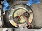
Replaced my fuel sender, but had to stop while i await a replacement rubber cover to replace the badly cracked one. While looking at the original cover, I noticed it has cut outs for the two electrical connections. But these sit at the wrong orientation of how the factory sensor was installed. This picture show the “o’clock” positions of the wires. The cut out holes don’t line up. Previously, the wires sat behind the rubber cover. Was the part molded with the holes in the wrong positions from day one? How are yours set up? Incidentally, mounting the flange in this rotational position places the float arm exactly downward, free to swing, no angle.
 

Attachments

  • F11D1695-9193-4347-AA59-6414837572A8.jpeg
    F11D1695-9193-4347-AA59-6414837572A8.jpeg
    324.9 KB · Views: 69
Here is a picture of my 78's wiring prior to removing the tank. Of course it is a carb car. I will look to see if I can find an FI picture. It's possible the holes were never changed for FI, which would mean they actually line up with the carb sender's fuel tubes.
1300_gas_tank_wires.JPG
 
Here is a picture of my 78's wiring prior to removing the tank. Of course it is a carb car. I will look to see if I can find an FI picture. It's possible the holes were never changed for FI, which would mean they actually line up with the carb sender's fuel tubes.
View attachment 64693
Hi Jim. Looks like yours is mounted another 72 degrees clockwise (one rotation of mounting studs) from where mine sits. I take it this produces no problems for you?

Update: I just received a picture from another X1/9 owner. It shows the connector position alignment to be just like yours. Now I beginning to wonder if A) the factory put it in wrong or B) prior owner replaced it and put it in wrong. So I'll pull it this evening and rotate it one stud position CW.
 
Last edited:
Hi Jim. Looks like yours is mounted another 72 degrees clockwise (one rotation of mounting studs) from where mine sits. I take it this produces no problems for you?

Update: I just received a picture from another X1/9 owner. It shows the connector position alignment to be just like yours. Now I beginning to wonder if A) the factory put it in wrong or B) prior owner replaced it and put it in wrong.
That carb tank is no longer in the car, but I am 99% certain that orientation was the stock set up. It was a one owner car prior to me and everything on it looked original. I would say that orientation never caused me any issues for 5 years before I pulled the tank.
 
I asked the same question several years ago and someone posted good pics of the correct orientation. It may have been Jim for all I remember. But see if you can dig up that old thread for more confirmation.
 
Hello Dr Jeff yes please could you try to find and post. I fitted a new sender a while back and suspect that the incorrectly set orientation is preventing a free swinging arm in my case. Even with the new float I never see more than half a tank on the gauge even with a tank's worth of fuel therein....unless certain arms have different resistor values...

Cheers

RDS
 
Here is the thread I was thinking of. It was for a carb engine/tank sender, but the FI one should be the same if you look at the location of the electrical connectors:


I think you also might be able to lift the sender up, hold it in the same position that you had it installed, and look at the movement of the arm to visualize if it would hit the tank walls.
 
  • Like
Reactions: RDS
Here is the thread I was thinking of. It was for a carb engine/tank sender, but the FI one should be the same if you look at the location of the electrical connectors:


I think you also might be able to lift the sender up, hold it in the same position that you had it installed, and look at the movement of the arm to visualize if it would hit the tank walls.
Dr Jeff, that close up in the linked thread is the same picture I posted in this thread above as a thumbnail.
 
I fitted a new sender a while back and suspect that the incorrectly set orientation is preventing a free swinging arm in my case.
On a carb'ed car with the feed / return pipes at the sender, it's (fairly) difficult to fit it in the wrong orientation as the pipes need to align with the corresponding holes in the rubber sender cover*. The JimD picture shows the correct positions (8mm feed uppermost and 6mm return directly vertical below, but all rotated about 10 degrees clockwise).

* assuming your rubber sender cover hasn't fallen apart 😬
 
Last edited:
On a carb'ed car with the feed / return pipes at the sender, it's (fairly) difficult to fit it in the wrong orientation as the pipes need to align with the corresponding holes in the rubber sender cover*. The JimD picture shows the correct positions (8mm feed uppermost and 6mm return directly vertical below, but all rotated about 10 degrees clockwise).

* assuming your rubber sender cover hasn't fallen apart 😬
My sender cover started cracking when the car was nearly new. I ignored it until a few years ago when I put the 1500 in. I removed it and found there was a substantial piece of steel inside side the rubber. I removed all the rubber, cleaned up the steel, and painted it. I put it back on and I think it looks as good as a rubber covered one, certainly better than a cracked rubber one. Last I looked, people were asking stupid prices for a new one.
 
I run without that stupid seal. Really, it just closes a hole that leads down into the gas tank bay so I'm not sure why Fiat even bothered with it. I guess a nice finisher would be pretty.
 
Here is the thread I was thinking of. It was for a carb engine/tank sender, but the FI one should be the same if you look at the location of the electrical connectors:


I think you also might be able to lift the sender up, hold it in the same position that you had it installed, and look at the movement of the arm to visualize if it would hit the tank walls.
Yes OK thanks I will investigate in due course, but I can hear a banging sound from the tank when cornering at speed.
 
On a carb'ed car with the feed / return pipes at the sender, it's (fairly) difficult to fit it in the wrong orientation as the pipes need to align with the corresponding holes in the rubber sender cover*. The JimD picture shows the correct positions (8mm feed uppermost and 6mm return directly vertical below, but all rotated about 10 degrees clockwise).

* assuming your rubber sender cover hasn't fallen apart 😬
No, seal is intact but not perfect. From memory i had to manipulate the arm and float in upside down for clearance then rotate to line up the tangs on the sender body.

I do recall measuring the resistances at different arm positions but the results were not what I was expecting.
 
No, seal is intact but not perfect. From memory i had to manipulate the arm and float in upside down for clearance then rotate to line up the tangs on the sender body.

I do recall measuring the resistances at different arm positions but the results were not what I was expecting.
Yes, you do need to apply light pressure to the arm to squeeze the assembly into the tank, but nothing that should distort it permanently.

What readings were you expecting? Iirc the gauge is something like 0 ohms when full, and 300 when empty, maybe a few more, with respect to the body. The warning light is a short circuit or thereabouts, open circuit otherwise.

Did your new unit look fundamentally the same as the old one, especially the size of the plastic float itself? What does the vendor say?

Edit: do you recall what way around the float was fitted? Looking at pictures of the carb and FI senders, the float pushes into the arm on different sides :rolleyes:
 
Last edited:
I'll have to dig out the reading and photos of the arm, I do recall that the resistance change was not linear, as the arm moved through its arc. However there was no float, I had to use one from a Fiat 500. Maybe the direction is incorrect but i recall that I fitted the unsecured end of the float pointed back to the arm so as to take up less space. I suppose there is no substitute for taking the sender out again....
 
I suppose there is no substitute for taking the sender out again....
Sounds like a plan. A quick Google shows a few 500 floats and they look longer than the X which is quite stubby in comparison. Odd to be sold a new sender without a float though... :confused:
 
A quick check of eBay using several alternative search terms for separate floats did not reveal anything suitable, frustratingly.

I would have thought floats were available separately.
 
Last edited:
The plastic floats on these are notorious for developing leaks, allowing fuel to fill inside to where they no longer "float". So a better alternative is to use a brass float. They are cheap, readily available, and will last a lifetime. Look for a old thread discussing that option. ;)
 
Will do but there is a rumour that our ethanol laced fuel attacks the solder in brass floats hence me avoiding them also.
 
Will do but there is a rumour that our ethanol laced fuel attacks the solder in brass floats hence me avoiding them also.
Interesting, I haven't heard that before. I'd be curious to see some actual evidence of that happening.
Here is an example of a brass float that fits the X's sender:
Brass Fuel Tank Level Float.jpg
 
Back
Top