Headlight relays

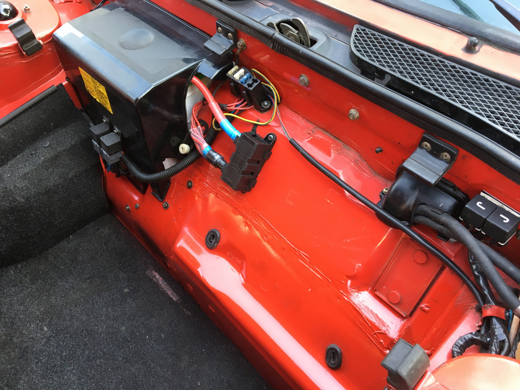
The VW part has fusible links (ie big fuses) as the links to the large outputs. The three to the side are fuses and would be good for feeds to the headlight relays and the wiper relays.

If you are near a pickapart or similar, this can be found on any 1999 New Beetle, Golf or Jetta through 2005 (longer on the New Beetle which stayed in production longer). While there you could savage the rest of the harness to get the factory made primary leads, particularly the connector for the three fused circuits with some length of factory wire.

MWB sells the grommet used for the wires to go into the cabin so if you wanted to run an additional heavy gauge wire into the cabin from this for the BWM it would make it clean and easy.

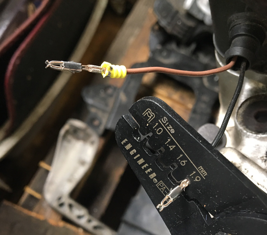
The link Dan offered, the items that company sells are excellent and accommodate either soldering or crimping. Given the limited space I really liked the right angle ones.

As you think about this and the easily available batteries (hard to find a 24F at times) you could ensure a modern broad application battery could be more easily accommodated with the cables making install and future compatibility easier.
 
Or skip all of this hassle and switch over to LED headlights. They are brighter and have a fraction of the power draw...

I did this a couple of years ago and it took me two tries to find the bulbs that like but now they are great. My volt meter does not move and the idle doesn't change when I am running the headlights. I think if you look up LED Headlights in the search you will see photos etc that I posted a while back..

Ed
 
As you think about this and the easily available batteries (hard to find a 24F at times) you could ensure a modern broad application battery could be more easily accommodated with the cables making install and future compatibility easier.
Great point; make the new cables to fit a better choice of battery. And if you replace the battery with a different (more available) model, consider a side post one. That way you don't need to use special post clamps, because you can mount a couple of cables directly to each of the side posts with a bolt.

Unfortunately mine is apart so nothing to photograph. And the following pics (from the web) are not great examples. But hopefully you get the idea.

Imagine more than one of these cables/ring end terminals (arrow) stacked under the mounting bolt:
side-connection-standard-cables.jpg


Sort of like on this odd configuration dual-post battery (but perhaps a cleaner job of it):
user55446_pic18958_1531948323.jpg
 
A couple of updates. A friend stopped by and suggested that the cranking when warm sounded more like it wasn't getting enough fuel. He gave it a little gas via the accelerator cable and we were able to get the car to start. He verified the timing is correct and we raised the idle and he suggested for the time being, when it's warm to depress the accelerator pedal a tiny bit to give it a little more gas to help it start. It's now started 3 times when warm. When the car cools off a bit, I have to keep the revs up to keep it idling. When the car is fully warmed up, it idles at around 2500 rpm. The idle was set when the car was well warmed up to the point of the car not stumbling at idle. But apparently that was too low for when the car is warm.

He suggested the car has a hot vacuum leak. I need to test it some more to make sure it'll start after being driven which I'll do soon. I drove it for about 45 minutes last night but wasn't able to try to restart it after giving it a heatsoak.

Is there a diagram of the vacuum lines anywhere? I've looked through the wiki but couldn't find it. Or has anyone experienced a problem like this before?
 
I didn't make any changes to the relay yet, but I did reconnect the wire that powers the relay in the headlight pod installed by the previous mechanic. When I was fumbling to reconnect the inline fuse in the headlight pod, I bumped the wire that runs from the battery to this inline fuse (that then runs to the relay), it shorted out against some other metal surface in the pod area. Lesson learned, I disconnected the battery and re-inserted the inline fuse into its holder so everything is connected.

But I didn't have any headlights. I pushed on all the relays as I had cleaned the contacts on them recently and lo and behold! got the headlights to come on. I thought I was good to go so I took the car for a test drive.

The headlights work, but if I got over a bump, they flicker off and on. If the bump is larger, they turn off - which is somewhat amusing in the middle of an on-ramp like it did last night.

I can hear a relay (or both?) in the fuse box area clicking each time the headlights flicker. The '79 wiring diagram shows 2 relays 00703 and 00704.

Is this a sign both relays need to be replaced?

This is a sign that the effing wiring approach is completely chuffed and should be tossed into the dust bin. The relays are clicking on and off as they lose either signal to be on or the power to run them.

Fix the wiring before you kill yourself.
 
Larry, when you depress the gas pedal actually you give more air (not more fuel) to a crancking motor..when restarting an hot motor it needs more air, that's why opening the throttle does help
 
The relays click and the lights are going out due to the wiring connections being intermittent. This is due to poor clamping pressure in the cheap crimp on connectors, wire lengths too short, not having the relays attached to a rigid surface, a ground which isn’t attached well or has corrosion, the power lead isn’t attached to the battery well or something else relating to poor workmanship.

Basically it isn’t a good install, I would strongly suggest pulling it all out and starting over.
 
Larry, when you depress the gas pedal actually you give more air (not more fuel) to a crancking motor..when restarting an hot motor it needs more air, that's why opening the throttle does help

Oh duh. I wrote gas when I meant air... and to think I make a (very very very) small part of my income as a writer.
 
In looking through the headlight relay install thread - https://xwebforums.com/forum/index.php?threads/headlight-relay-installation.14247/ - this photo shows the wires running through the frunk. But on my '79, those openings on the sides of the photo don't exist which I assume is why the power wire from the battery was run through the weatherstripping since there was no other easy place to run it.

Any suggestions on where to run the power wire? In the past in non-automotive applications, I've used the plastic wire clamps with sticky tape on the back but the sticky tape seems to last about a day before it gives up. Inside the frunk, I don't have a lot of confidence in it.
 

Attachments

  • Screen Shot 2019-08-10 at 10.07.35 AM.png
    Screen Shot 2019-08-10 at 10.07.35 AM.png
    573.6 KB · Views: 100
I did what Karl suggested in terms of adding a fuse block feed directly from the battery, feeding a pair of SPDT relays which I mounted to the battery cover.

The problem with US generic crimp connectors is the connection is shite. Unless you get the type that match the factory crimp (open jaws, folded over the wire & in-between when crimped) , I say it's safer to solder the wires.

E621-C3-EA-CF49-4129-82-AA-FBD9-C70762-F6.jpg


This style crimp - that holds the wire and the insulation (and seal in this specific instance, first pic of mine I could locate to illustrate the point):

IMG-8550.jpg
 
Last edited:
The problem with US generic crimp connectors is the connection
In addition, I'll also add that I'm not fond of "push on" type connectors of any type. I'm talking about any of the ones that have some form of this interface between the two connector components (flat, round, whatever shape):
push_on_terminals.jpg

I prefer something that is secured by a screw or other form of locking interface. That could be a ring terminal and screw, multilead connector block with locking tabs, or others.
b-connectors.jpg
pt_wireconnectorspigtails.jpg
8186202fb37f77ad4e428874f78ab160b036.png


If you look you can find fuse blocks with screw connections for the leads rather than push-on ones.
71wq4d5n+tL._SX466_.jpg
 
I did what Karl suggested in terms of adding a fuse block feed directly from the battery, feeding a pair of SPDT relays which I mounted to the battery cover.
What do you do when you remove the battery cover? Can you actually remove it from the car?

The problem with US generic crimp connectors is the connection is shite. Unless you get the type that match the factory crimp (open jaws, folded over the wire & in-between when crimped) , I say it's safer to solder the wires.

E621-C3-EA-CF49-4129-82-AA-FBD9-C70762-F6.jpg

I like what you did here running the wire across the frunk to the passenger side wire bundle.

This style crimp - that holds the wire and the insulation (and seal in this specific instance, first pic of mine I could locate to illustrate the point):

IMG-8550.jpg

Where do you get them from? We used to have an electronics supply store here that I'm pretty sure would have carried them, but they closed up last year.

OR would it be better to solder the wires together and cover with heatshrink tubing and electrical tape instead?
 
Last edited:
The openings exist under a plastic cover on the right side of the frunk

Ah.. so they do. I didn't see them earlier.

But when the wire goes into the passenger footwell, I don't have a power bar - I've got the original '79 fusebox. Um... where do the wires connect?
 
And one more...The yellow wire coming off of this runs to the bottom right corner of the relay for the (sort of British car sounding) air horn. The Yellow to Blue wire is the wire from the battery to the inline fuse to the relay.

So I'm assuming the installer used 1 relay for both the headlights and the air horn. My plan is to reuse this relay but make it for the airhorn only and nothing else. I haven't had much luck finding a project box, however some small plastic food storage containers from the kitchen might work very well instead.
 

Attachments

  • air-horn.jpg
    air-horn.jpg
    185 KB · Views: 40
It is never easy to unwind work previously done, this one seems especially odious. I apologize for reiterating but you really need to start over by identifying what you have and planning a means of fixing the problems you find. Don’t try to reuse components as the quality of the previous mechanics work will affect your work and his work was not good.

The car already has a horn relay so they used the existing horn wire. You can’t use one relay for more than one task, ie turning on the lights and running the horn on demand.

Putting unprotected relays into the headlight pod is a poor approach as the ones you have are not water sealed units in addition to all the poor connectors used to joint everything.

One can solder and heat shrink but service becomes difficult and there are issues with solder due to vibration breaking the hard joint or the wire to either side of the hard joint.

NAPA sells quality connectors and there is of course the internet. NAPA is your better choice as it is hard to know what you will get from Amazon etc from a quality standpoint.

I would add the fuse holder I linked to earlier which gives you four power sources and I would place the new relays next to it. I wouldn’t attach the relays to the battery cover, you are running wire one way or the other so I would install the relays to the structure of the car near the battery.

I have attached the wiring diagram for the lighting and the horn system below.
 

Attachments

  • 79Wiring,05.pdf
    424.9 KB · Views: 42
Yeah, I forgot that I moved them off the cover & set them below. The cover could be pivoted off the battery the way I had it previously, but in the event the cover needed to be removed entirely I had to unscrew the relays first.

I buy terminals from Mouser. Thing is, I have dozens of Volvo-supplied locking terminal housings, so I buy the terminals that match those. Like Jeff, I dislike standard no-lock spade type connector housings of the type used by Fiat back then.
 
Back
Top