Inexpensive headlight relay kit from Amazon

JimD

Waiting for Godot...
Moderator
I have been working my way through upgrading the lighting on my 85X. This past week I installed LEDs in the tail lights, front and rear turn signals and reverse lights. I put the proper LED flasher in the relay tray. Somehow, I forgot to order the marker LEDs and license plate LEDs. I will get the markers, but I think I may leave the license bulbs stock. The recommended LED didn't fit very well in the housing.

Today, I finally got around to installing the headlight relay kit I got off Amazon for about $20.00USD. I decided to try the Amazon set, since I had used a similar Ebay set on the 124 Special a few years ago. The kit is not as well made as Bob's kits, and some wires needed to be extended or have their terminators snipped and swapped for something more appropriate.

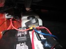
Anywho... It took me a few hours to work thru the process. I put the relays in the passenger side pod, because there were easily accessible wire grommets to use for routing the power wire to the battery. I ran a 10ga wire from the battery into the pod and attached it to the kit's power wire that had a 30a fuse holder installed. My 85 had two little dimples stamped in the pod ahead of the position where the ground blossom is installed. I drilled the forwardmost dimple and bolted the relay set inside the pod.
IMG_2115.JPG IMG_2116.JPG

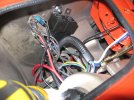
There was plenty of wire between the two head light connectors to reach between the headlight pods. I did have to remove the kit's headlight connector for the "remote" headlight in order to get the wires thru the grommets in the pods. I zip tied the headlight wires to the stock loom that passes between the pods. Horrible picture, I should have taken a picture when the car was in the air. The thicker and cleaner blue and white wires towards the top of the picture are the high/low beam wires running from the relay set to the driver side headlight.
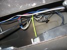
IMG_2118.JPG

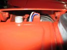
The biggest concern I had was the headlight connectors themselves. The X has 90 degree wire connectors to provide a little wiggle room. The kit's connectors are not 90s and I was a little worried that I wouldn't be able to get them on without pulling the headlights. I managed to carefully get them on, but then I was worried the wires would rub on the headlight bucket or the pod's cross support in operation. Thankfully it all worked out and none of the wires is rubbing. You can see there is some clearance between the bucket and the wires on the connector. I will probably go back through and see if there are places that might benefit from another zip tie or two for wire management.

Driver side:IMG_2114.JPG Passenger side:IMG_2119.JPG
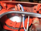
Prior to all this light upgrading, my volt meter would drop significantly when the headlights were on, or brakes were applied. It would swing up and down with the blinkers. If it rained, I just left the wipers off. Try any combination of the above and the volt meter would bottom out. I took a test drive this evening after finishing up and now the voltmeter barely moves no matter which lights I turn on. I am sure the blinkers would still make the VM unhappy, but that is a task for another time.

As I was leaving the garage, I noticed there are lots of open hoods and engine covers. Lots of little tasks to take care of on each car.
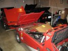
IMG_2121.JPG
 
Where did you get your LEDs?

I would bet that now that you are using a IC based flasher relay vs the old style you will likely see an improvement from that as well on your volt meter.

Due to the arrangement of the voltmeters wiring it never really indicates the actual charging unless accessories were off, running nearly all the accessory power through the ignition switch really messes with the overall indication shown by meter.
 
I got the LEDs and flasher from superbrightleds.com. They are located a few miles from my house, but I ordered online.

With the new flasher the VM needle doesn't dance to the beat of the turn signals anymore.
 
I like Superbright, I have been a commercial customer of theirs for many years. They have come through on some crunches for a few times. Good company in my experience.

What didn’t you like about the license plate bulbs in regards to fit up?

This has been on my list for a few seasons now for both my X and more particularly the 850 as its electrical are decidedly weak…

Thank
 
The license plate and brakes take the same bulb, white for the license and red for the plate. The bulb from superbrightleds has a glass dome over the led cluster. Probably because some license fixtures have an exposed bulb. That glass dome makes the led unit taller than the stock incandescent bulb. The led unit would not fit properly in the X housing.

I need markers still, so I will look at some other vendors for license options.
 
The bulb from superbrightleds has a glass dome over the led cluster.
That is likely a "diffuser" lens to broaden/disperse the normally unidirectional/focused light pattern from LEDs. You can get the same type bulb without that dome top. It will have a narrow beam but should be fine for the license plate application. Or there is a version with a convex lens to help disperse the light. That one doesn't stick up quite as far and might clear the housing?
 
OK, a little update on the license plate lights. I re-read some of the posts on Xweb that gave the list of bulbs needed for the various locations. This time through I noticed that the recommendations for the brake lights (1156 red) AND license plate lights (1156 white) are for "forward firing" LEDs. I had ordered the domed version. So I ordered the new LEDs and now the bulbs fit the license plate housings. If you look at the two bulbs, the forward firing is shorter than its domed counterpart. So get the forward firing style as it is basically the same height as the original incandescent bulb.

I got the side marker lights in this order too. The marker sockets on my 85 are a little flaky, but I got them working. The right rear light had a bad ground, so I had to make a new ground wire for that corner. Both fronts required me to push the bulb in, then gently pull out on them till they lit up. No matter what I tried, they would not light if they were completely seated in the socket. Weird. o_O
 
I recently installed this relay set based on the Jim D recommendation. My skill set is a solid “mediocre”, but I may have a few details to add that others might find useful.

First, I removed the frunk carpet, and the plastic cover along the passenger side of the frunk which covers the existing wire bundle to the front of the car (2 screws for the cover).

I placed the kit relays under the plastic cover, and I routed the kit wires to the driver side lights along the front edge of the frunk to an existing hole into the headlight pod (near the horn). From there I simply pulled the original socket off the headlight, and plugged the new socket onto it.

For the passenger side I had to cut the wires for the kit and add extension wires. The extensions could be forced through the existing rubber grommet from the frunk out near the radiator. From there I forced the extensions through a different grommet into the headlight pod. Then I crimped the extension wires onto the new sockets that I cut off the new kit. Plus I crimped on new .25 inch female spade connectors onto the kit’s ground wires for both headlights and plugged them onto open male spades on the existing ground blooms.

Then I ran a 10 gauge wire from the battery to a spade connector, and crimped in a compatible connector onto the kit’s power line.

Finally, I replaced the plastic cover and carpet in the frunk, and the lights works as intended.

I did have one bad crimp to the passenger high beam that I had to do a second time, but otherwise the biggest challenge was finding and using the existing grommets to the passenger side so that I did not have to drill any new holes.

I think I spent more time figuring where to route the wires than actually doing the install.

Good luck
 
Then I ran a 10 gauge wire from the battery . . .
As someone with sub-mediocre skills, I've been wondering: what's the best way to do this? Do you replace the entire positive battery lead thing that clamps onto the post? Just wrap the new wire around the old clamp or one of the existing hot wires?
 
As someone with sub-mediocre skills, I've been wondering: what's the best way to do this? Do you replace the entire positive battery lead thing that clamps onto the post? Just wrap the new wire around the old clamp or one of the existing hot wires?
I put a ring terminal on the end of the new 10ga wire and put it under the nut on the positive post clamp. I have 3 or 4 wires clamped on there now. The PO of my 85 has an additional fuse box on the driver's side of the frunk that I could have connected too, but I just stopped at the battery. They do sell positive terminals designed to neatly accept accessory wires and DanS has a nice write up on adding a centralized power distribution post that hides the extra wires behind the dash. Lots of options, I took the easy way. :)

Here is a picture of the madness that is my + post. 😈
IMG_2126.JPG
The big blue wire might be for a stereo which doesn't work. The red heading towards the driver's side goes to the additional fuse box. The red coming straight at the camera is for the quick connect on the battery tender and the red dropping off the front of the battery is heading to the passenger side pod for the headlight relays. Somebody should clean that mess up... someday. :)

I often wonder what is connected to the additional fuse box. I have never traced the wires coming out of it. Probably stereo stuff as there is evidence of a sub woofer living in the spare tire well at some point in the past.
 
Last edited:
There's a couple of options for adding more power wires to the battery post.

You can use a "marine" type clamp which allows more than one cable to be connected. There are several versions of them:
71MgF8bimzL._AC_SY355_.jpg
Heavy-Duty-Car-Vehicle-3-Ways-Battery-Terminal.jpg


They use cables with a ring terminal end, so more than one can be attached:
National-Luna-Battery-Multi-Terminal-01.jpg
Terminals_Heat_Shrink.jpg


I like to use a side-post style battery with ring-terminal cables. Then I replace the standard cable connector with a bolt so multiple cables can be attached (this isn't the exact same but gives the idea):
download.jpg


Or you can use a cable with a second power lead already attached. Then run that extra lead to a terminal post like has been suggested:
61Asubn13HL._AC_SX355_.jpg
81Y2A-BdqoL._AC_SX522_.jpg
 
I recently installed this relay set based on the Jim D recommendation. My skill set is a solid “mediocre”, but I may have a few details to add that others might find useful.

First, I removed the frunk carpet, and the plastic cover along the passenger side of the frunk which covers the existing wire bundle to the front of the car (2 screws for the cover).

I placed the kit relays under the plastic cover, and I routed the kit wires to the driver side lights along the front edge of the frunk to an existing hole into the headlight pod (near the horn). From there I simply pulled the original socket off the headlight, and plugged the new socket onto it.

For the passenger side I had to cut the wires for the kit and add extension wires. The extensions could be forced through the existing rubber grommet from the frunk out near the radiator. From there I forced the extensions through a different grommet into the headlight pod. Then I crimped the extension wires onto the new sockets that I cut off the new kit. Plus I crimped on new .25 inch female spade connectors onto the kit’s ground wires for both headlights and plugged them onto open male spades on the existing ground blooms.

Then I ran a 10 gauge wire from the battery to a spade connector, and crimped in a compatible connector onto the kit’s power line.

Finally, I replaced the plastic cover and carpet in the frunk, and the lights works as intended.

I did have one bad crimp to the passenger high beam that I had to do a second time, but otherwise the biggest challenge was finding and using the existing grommets to the passenger side so that I did not have to drill any new holes.

I think I spent more time figuring where to route the wires than actually doing the install.

Good luck
Do you have a link to the Amazon kit you purchased? The previous link from JimD seems to be dead. Thanks
 
Thanks - I've been looking at them all day. It's always good when you find one that's tried and tested though. Watched some YouTube videos as well. Is the X19 as simple an install as a Jeep or Tundra?
Pretty much. The biggest issue is placing the main power wire to the first pod. Then going across the radiator housing to the second pod with the wires. You may need to remove the wires from the connectors to feed them through existing holes and possibly extend a wire or two (most likely the main power wire to the fuses depending on how they set these up).

As this isn’t made specifically for the X you will likely run into issues of one sort or another particularly due to the fact you have to go through multiple bulkheads/steel surfaces, you aren’t just laying it into an engine bay.

To be clear, I haven’t bought any of these and know nothing of their quality.
That‘s what I was wondering - how much faffing around was required, aka would it be just as much/little work to wire up your own design. Can’t beat the prices and simplicity though…
 
Last edited:
I have found sometimes that just the component prices are higher than these assemblies.

Extending a wire or removing a wire from the connectors are not that arduous, just require some time and patience.
 
I have found sometimes that just the component prices are higher than these assemblies.

Extending a wire or removing a wire from the connectors are not that arduous, just require some time and patience.
After looking this over, and looking over the 74’s wiring pods, my question is: where is the single, power connection on the exxe that the circled connector goes to - is it a combination of wires hitting one of the factory relays, because if there’s a single, master, headlight connector, I haven’t found it. In their description it’s called the “vehicle headlamp socket”, or the “vehicle wiring harness”. Guessing I still won’t get any assistance from Mo.? ;)

DE38C523-00A1-47B4-96F2-8FB9E4C3F71E.jpeg
 
Last edited:
Back
Top