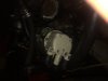
As Rachael said, there in shadow is another sender for “low pressure warning light”.
O.K., there are two separate senders on the engine block? The one you showed and another one that was hidden in the shadow? If so, then I think it should be like this (hope one of the UT experts can confirm):
The sender in the shadow (described as for the warning
light) will have one wire to it. That wire goes to the dash warning
light and tells you when the oil pressure gets dangerously low (last minute warning).
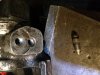
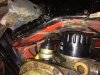
The sender you show in pictures would also have only one wire to it and is for the
gauge on dash. This tells you the actual oil pressure all the time (constant moving). Therefore this sender should be the one with only one terminal on it (see photo below).
Both senders in photo above will fit the block, both will have a terminal for the gauge, so either could work. However if you use the one with TWO terminals, then need to determine which terminal is for the
GAUGE (other terminal will be for the
light, but not used here because the light has a separate sender...in shadow). The writing on the these two senders will be very similar because they are very similar senders...but one has extra function (not needed here). If the sender with two terminals was in the engine block, then either it was installed in a car with a different wire harness (two wires to this sender and no second sender in shadow), or a previous owner installed the wrong sender...should have been one with only one wire.
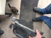
I am guessing the OTHER sender for the
warning light (hidden in shadow) will be a small type, looks kind of like this:

So if your wire harness has one wire that reaches the large sender (in your pictures), and one wire that reaches the small sender (hidden in shadow, looks like last picture), then you are good....connect one wire to each sender. If the warning light and pressure gauge both do not work correctly when connected this way, it could be possible the two wires are reversed; swap them between the two senders and see if the gauge and light work correctly. Both use the engine block for ground and both connect this ground through the sender to the wire connected to it (neither is positive), so no chance of short circuit here. The small sender (in shadow) is a "open or closed" connection...when oil pressure drops below a pre-set level, the sender connects the ground to the light on the dash (other wire to dash light is positive). The large sender (in your pictures) has a "variable" connection...as oil pressure changes, the amount of resistance from the ground changes, this gives the gauge a variable negative signal to display (the other wire to the gauge is positive).
")