Selling the X & Bought an 75 Datsun 280Z

OK, I can sleep at night now.
My last Datsun experience was in the late 70s helping my soon to be wife's idiot girlfriend to get her Datsun B210 running right. I spent a whole afternoon trying to get it running and wondering why the exhaust smelled so bad...........she then tells my she had put diesel fuel in by accident. I still get migraines about that day.
 
Visited a friend's garage today and thought you might be interested. He was preparing his 240z for next weekend's race.
I didn't realize that the engine is very like our SOHC. I expect an X-flow under the bonnet 😮.
This one is fast.
1687879036306.jpeg

1687879087499.jpeg
 
Finally got back to this - assembled & installed the rear bumper today. I test-fitted it yesterday & marked the 2 drill locations for the side attachments. Primed & painted the holes prior to assembly. Had to do it jammed in the garage, it rained all day.

I had to retap both the side captive nuts - neither would accept the M12x1.25 bolts.

Also had to use 3M VHB tape to secure the rubber strips - otherwise they 'flop' away from the bumper in-between the mount studs. I had removed the fronts & done the same previously. The vendor claims you just have to pull the rubber & then tighten in place. That would work if the bolt holes were elongated, which they are not.

PXL_20230627_144245676.jpg

The right side I had to shorten the bolt & grind the tip to a point to guide it into the bumper bracket. Not much room given the gas tank proximity

PXL_20230627_153054127.jpg

PXL_20230627_153124214.jpg

Made sure both sides were level - holes were about 9" down from the side molding, and about 5.5" forward of the existing bumper side mount captive nut

PXL_20230627_153336149.jpg

PXL_20230627_153323178.jpg

My phone is fk'd - makes it difficult to gauge what I'm shooting. been waiting a week now for a shipping notice on the replacement from Google FI
PXL_20230627_114441291.jpg
 
Took out the glovebox today, so I could see what's back there regarding the heater & AC

PXL_20230630_201808339.jpg

pulled the blower housing, made it very easy to access all the heater hoses. Needs a good clean anyway.

PXL_20230630_201344618.jpg

PXL_20230630_204754452.jpg

Heater core out.

PXL_20230630_204747844.jpg

bulkhead fitting removed, M4 rivnut in place to retain the AN line fitting

PXL_20230630_220323566.jpg

turns out the aluminum bracket/fitting has identical spacing to factory, makes things easier. Just have to drill the center hole to match the factory cover plate shown

PXL_20230630_214824531.jpg

PXL_20230630_221252411.jpg

All kinds of crusty 'plastic' laying in the box - it seems the heater core end tanks were encased in it

PXL_20230630_221330115.jpg
 
Last edited:
So to continue with my version using the escort heater core (thanks to Capt. Obvious on ClassicZ) I ordered the heater valve mentioned by another -4 Seasons 74627 - but it didn't arrive until late this evening, so I dismantled the original & had a go at fixing it following the other thread on ClassicZ

Think it's pretty clear why the heat never shut off

PXL_20230701_143748302.jpg

I forgot to take pics of the re-assembly, I used a Viton o-ring in place of the square cut outer seal, I left the inner one alone. Left it set on an angle filled with fluid to check for leaks.

I flipped the I/O for the heater hoses - the bulkhead upper is now the return & the outer/lower is the feed. I did it this way so that the feed is not too short, and the return is a straighter run. and so the inside feed is a plain elbow 90º. Determining hose lengths here. An -10 fittings. SS pipe length is 20.5".

PXL_20230701_184009491.jpg

dogleg for the other end, test fit alignment of pipe & hoses

PXL_20230701_184013926.jpg

Hoses cut & clamped (head fitting was removed, de-rusted, sealed & reinstalled, slight offset change -more vertical

PXL_20230701_200658096.jpg

Far end adjusted & clamped

PXL_20230701_200700377.jpg

PXL_20230701_200703493.jpg

With that end out of the way, I returned to the heater valve & core (91-02 Ford Escort). Eyeballed holes for core pipes, based on the core being centered Core sizing comparison pics (copper version, slighlty smaller core than the aluminum). Added closed cell foam on the sides to make it snug, and to the front to keep it pushed all the way in & cover up the old pipe holes.

Was playing with hose routing - this way was to allow the 74627 straight pipe valve to sit above the feed pipe

PXL_20230701_193204497.jpg

PXL_20230701_193211909.jpg

along these lines

PXL_20230701_193113546.jpg

I'll revert to this layout if I need to switch to the 74627 valve

PXL_20230701_193119215.jpg

When it became clear that the 74627 wasn't coming , I switched gears & worked on fitting the original repaired valve -

Heater valve fitted using the upper existing mount screw, new hole drilled in plate. Cut a notch in the valve mount bracket to clear the lower screw. Checked that flap can open.

Feed hose clamped. Cable attached & function tested.

PXL_20230701_214527933.jpg

Test fitting (formed, Volvo) hoses to & from heater valve

PXL_20230701_214808153.jpg

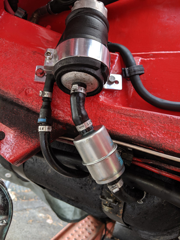
Added oetiker clamps after this. Since I wasn't able to flare the end of the core tubing, I prefer them as the clamping is typically more uniform than a worm clamp of any type.

PXL_20230701_214803289.jpg
 
Last edited:
Couple days ago I re-pinned the center console harness connections
PXL_20230703_164139362.jpg

added some low temp electrical grease
PXL_20230703_202301698.jpg


Started pulling apart the rear suspension after work today. Had to remove the exhaust first - since it's all one piece from the DP flange to the tailpipe, I cut it behind the cat. I'll add a junction there - maybe a V-band, or just a sleeve clamp. Ultimately the whole exhaust will be custom with the VQ35DE anyway. Looked over the undercarriage in general since this is the first time I've been under the back end

Control arm bushing are all bad
PXL_20230705_191003153.jpg

PXL_20230705_191326554.jpg


Tapered pin that retains the outer control arm bolt
PXL_20230705_192807626.jpg

They came out without any drama. I had ordered new main bolts & these, as they typically are a problem. Murphy's Law - if I hadn't bought the new hardware, I would have needed it..
PXL_20230705_224430447.jpg


Damper on diff mount/control arm forward bracket had stripped bolts
PXL_20230705_192754964.jpg

The diff mount is an absolute PITA to remove - the retaining bolt heads cannot be accessed with a socket - the lower half of the mount interferes. They also don't thread into the casing -there are 17mm head nuts that have to be counter held.
PXL_20230705_221318891.jpg

had to re-tap to M10x1.5 , to avoid replacing the captive nuts or helicoils
PXL_20230705_223724844.jpg

exhaust - still has the original shielding
PXL_20230705_191214053.jpg

PXL_20230705_191923306.jpg

PXL_20230705_191929200.jpg

Shield over rear bumper shock
PXL_20230705_191542005.jpg

original rear hanger
PXL_20230705_205138544.jpg

cut just behind cat

PXL_20230705_205144847.jpg

PXL_20230705_205628711.jpg


Floors
PXL_20230705_191251891.jpg

PXL_20230705_191256188.jpg

PXL_20230705_191439575.jpg

Poorly installed fuel feed hose - pretty heavy kink
PXL_20230705_191054682.jpg

Limiter strap over top of diff snout
PXL_20230705_191403906.jpg

PXL_20230705_192800250.jpg


Hopefully get more done on it tomorrow
 
Last edited:
Trying to figure out which way to go with the rear exhaust section. Ultimately, it will have the VQ35DE, so that will require a Y off the headers into a single rear section.

So, since the front dual exhaust will all be 2.5" (once the VQ35DE is fitted), would it behoove me to make the rear section 3" after the Y, or can I get away with 2.5"? This will be staying NA.
It will be easier for me to fit 2.5" without much loss of ground clearance. 3" may present issues.

The plan is to make it modular - L & R headers - dual cats - Y - single exhaust/resonator/muffler/tailpipe
So, for now, I want to make the rear section that will fall after the Y large enough that I can just fabricate the front section for the V6 when the time comes. The current exhaust is all 2"
Unless keeping it 2.5" after the Y will create significant performance issues, that would be my preference.
Thoughts?
 
Did the mustache bar bushings and the inner control arm bushings. If I can't extract the outer c/arm bushings in-situ tomorrow, I'll have to drop the arms entirely. Forward bushings are longer than the rears.
PXL_20230706_181825551.jpg


For mustache bar, the original bushing sleeves need to be kept, so I holesawed the rubber out & wire brushed the sleeve of residual rubber
PXL_20230706_194257351.jpg


rear bushing sleeves came off with just a little soaking. Didn't take the time to clean the diff cover at this time.
PXL_20230706_194450890.jpg


PXL_20230706_213003492.jpg


PXL_20230706_213015121.jpg


old remnants
PXL_20230706_213901035.jpg
 
Last edited:
Trying to figure out which way to go with the rear exhaust section. Ultimately, it will have the VQ35DE, so that will require a Y off the headers into a single rear section.

So, since the front dual exhaust will all be 2.5" (once the VQ35DE is fitted), would it behoove me to make the rear section 3" after the Y, or can I get away with 2.5"? This will be staying NA.
It will be easier for me to fit 2.5" without much loss of ground clearance. 3" may present issues.

The plan is to make it modular - L & R headers - dual cats - Y - single exhaust/resonator/muffler/tailpipe
So, for now, I want to make the rear section that will fall after the Y large enough that I can just fabricate the front section for the V6 when the time comes. The current exhaust is all 2"
Unless keeping it 2.5" after the Y will create significant performance issues, that would be my preference.
Thoughts?
They do make 3” Y back to the muffler which starts at the tail piece of the transmission.

 
Dropped the struts/hubs after work, no drama. All drum brake parts removed. I don't want to hack up the back plates, so I'm going to pull the spindles.

PXL_20230707_184512051.jpg

This Volvo tool (999-2846) intended for old RWD prop shafts fit the Z U-Joint

PXL_20230707_180715922.jpg

PXL_20230707_180652353.jpg

PXL_20230707_184914175.jpg

PXL_20230707_192048801.jpg

Hopefully I'll have the hubs apart tomorrow, and replace the strut inserts and coil springs

PXL_20230707_194119074.jpg
 
They do make 3” Y back to the muffler which starts at the tail piece of the transmission.


I saw that late yesterday when looking - so 3" should fit under the crossmember OK. The only downside is I already have a couple nice 2.5" I/O mufflers from the X1/9 noise trails (following Rodger). I could run 3" pipe from the tunnel (where the Y would fall), make a step adapter on one of the 2.5"mufflers. That way, DTR, I can always just swap out the muffler for a 3" I/O to go with the VQ35DE drivetrain. The L28 certainly doesn't need it.
 
Also dropped the (aftermarket) fuel pump & feed hose today. I don't like the way the pump is fitted either.

fuel hoses.jpeg

redrilled the mount plate to move the (new Bosch) pump up & out the way somewhat, adding Quick -Release fittings, to get rid of the large loop

PXL_20230707_211846334.jpg

PXL_20230707_212101957.jpg

Volvo fuel hose 1312257 11.5mm ID sold by the meter

PXL_20230707_212110460.jpg

PXL_20230707_212617259.jpg

Have to fit the pulse damper above. I won't need it with the VQ35DE install, so I'm going to make it easier to remove

PXL_20230707_212614127.MP.jpg

PXL_20230707_212604545.jpg
 
Also dropped the (aftermarket) fuel pump & feed hose today. I don't like the way the pump is fitted either.


PXL_20230707_212110460.jpg
Is there enough run to put an inline filter in or are you at all concerned given what you have found in the lines relative to rust etc?

I have seen you use these quick disconnects in the past, where do those come from?
 
Is there enough run to put an inline filter in or are you at all concerned given what you have found in the lines relative to rust etc?

I have seen you use these quick disconnects in the past, where do those come from?
Let me guess, A Volvo????
 
I bought inline filters- but both had the wrong OD pipe. I want one there, even though there is no evidence of crud in the system.

Thought I was getting one the same as this
IMG-20191013-165559.jpg

Volvo uses the QR fittings for a variety of fuel & cooling/heating applications, but this particular style I buy either off eBay or on Aliexpress, much cheaper that way

Standard fuel size for most 4 cylinder applications would be 6.3mm ID I've bought a range of larger versions to use for heater fittings on the V8, and for the larger fuel lines on that also - for 10mm ID hose and 12mm ID hose, and some even larger
Is there enough run to put an inline filter in or are you at all concerned given what you have found in the lines relative to rust etc?

I have seen you use these quick disconnects in the past, where do those come from?
Let me guess, A Volvo????
 
Last edited:
  • Like
Reactions: 86X
I bought inline filters- but both had the wrong OD pipe. I want one there, even though there is no evidence of crud in the system.
Volvo uses them for a variety of applications, but this particular style I buy either off eBay or on Aliexpress, much cheaper that way

Standard fuel size for most 4 cylinder applications would be 6.3mm ID I've bought a range of larger versions to use for heater fittings on the V8, and for the larger fuel lines on that also - for 10mm ID hose and 12mm ID hose, and some even larger
That opens a whole new world. Thanks!

I notice you have used the nylon hose in the past, do you have a tool for assembling the nylon line to these connectors?

I see things like these: https://hackaday.com/2022/05/11/caulking-gun-becomes-useful-press-tool-for-fuel-line-fittings/ or similar as a low cost way to press the fittings in.

I bought this one last fall, however I have always just done it by hand - either tap the barb in to the tube by hand, or hold the tube in a brake line flare tool & tap the barb in that way. Worked fine for all the straight & 90º fittings. Not so much for 45º, 60º etc., so I broke down & bought the tool.
 
Finished up the fuel pump/pulse damper install today

Used some preformed nylon line cut from a Volvo, mostly likely. That put the pulse damper where it needed to be to connect to the feed hard line

PXL_20230708_152437811.jpg

PXL_20230708_154642996.jpg

PXL_20230708_154658698.jpg

With that figured out, I made a bracket to support it welded to the fuel pump bracket

PXL_20230708_162134459.jpg

hook up the pump wires before installing the assembly

PXL_20230708_162721581.jpg

PXL_20230708_163446595.jpg

All up out the way now

PXL_20230708_163505051.jpg

Installed the correct return line , that was also the wrong ID

PXL_20230708_164657884.jpg

PXL_20230708_165932695.jpg
 
Back
Top