Selling the X & Bought an 75 Datsun 280Z

Had a little time to work on the dash today, so I put the frame in the car to figure out the right side support brace

Left side brace sits right up against the box

PXL_20230816_200329496.jpg

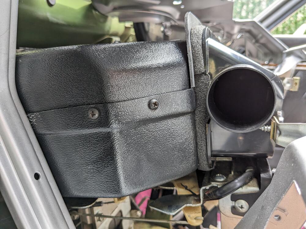
Right side - definitely was removed due to Evaporator

PXL_20230816_200517083.jpg

PXL_20230816_200523772.jpg

set the glovebox in place, to check clearance outside the evaporator box - none

PXL_20230816_201023600.jpg

Used a aluminum ruler to make a brace

PXL_20230816_205511614.jpg

I'll add an angle bracket back to the dash frame, to attach the brace to

PXL_20230816_205252654.jpg

frame back out to finish up the angle bracket for the brace & add spot welds to the existing structure

PXL_20230816_220756967.jpg

PXL_20230816_220355563.jpg

PXL_20230816_220358364.jpg

PXL_20230816_220412112.jpg

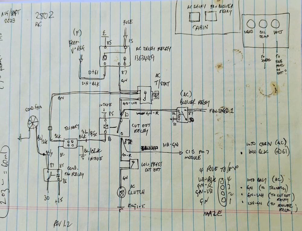
Going to replace the fusebox with an MTA 15 ATC fusebox, and a (4) relay panel

PXL_20230816_210909116.jpg

l
 
Worked on the AC lines from evaporator to firewall, sealing the box, and sealing the ductwork to the box. Fitted the dash frame to check all fitments

PXL_20230817_173415283.jpg

have to crimp the fittings

PXL_20230817_173420918.jpg

PXL_20230817_173427637.jpg

sealing foam for lines exiting the box

PXL_20230817_164156730.jpg

closed cell foam to seal box to frame attachment

PXL_20230817_164203802.jpg

test fitted evaporator box & dash frame

PXL_20230817_181138863.jpg

gap around duct housing

PXL_20230817_182353881.jpg

Even worse on the right

PXL_20230817_182359092.jpg

added a flange to mate with the Nissan duct, so I could seal the gap. Factory evaporator box must be taller & narrower.

PXL_20230817_192646357.jpg

extra thin foam on top half, due to angle of evaporator box

PXL_20230817_200927677.jpg

Added thick foam to the duct, to seal against the flange

PXL_20230817_193107329.jpg

PXL_20230817_193137126.thumb.jpg.dd3abc820422fb1f1e07491cfdadbc25.jpg


PXL_20230817_193304387.jpg

then added thin foam to seal the facia vent to the duct

PXL_20230817_200924068.jpg

PXL_20230817_201016027.jpg

sealed now

PXL_20230817_201049849.jpg

PXL_20230817_201208818.jpg

Have to repaint the silver edging on these

PXL_20230817_205436752.jpg
 
Last edited:
Touched up the silver edging

PXL_20230823_013317388.jpg

Test fitted the compressor & mount. It will have to be raised age least an inch. Rear lower mount sits on PS rack. Stock Datsun AC belt length will be OK (13x875).

PXL_20230822_201346221.jpg

PXL_20230822_201338773.jpg

PXL_20230822_201332197.jpg

Have to figure out the best place to drill through for a harness for the AC stuff

PXL_20230821_212030575.jpg
 
reworked the mount plate, set all holes 1.5" below original; had to add an ear for the rear lower mount point.

PXL_20230823_170526067.jpg

back in place, with earth strap for compressor

PXL_20230823_170839297.jpg

compressor in place. Belt could be 25mm shorter, but still have enough range as it is

PXL_20230823_174003938.jpg

belt alignment and clearance all around looks good

PXL_20230823_174012794.jpg

PXL_20230823_174021559.jpg

PXL_20230823_174026349.jpg

With that aspect done, I worked on the condenser mounting & high pressure hose fitting. Low press hose will be shorter

PXL_20230823_185115495.jpg

made standoffs (set 1.5" off the bulkhead) to secure the condenser, one with 3 M4 screws on the right, 2 separate ones one the left; upper with one screw, lower with two.

PXL_20230823_215850029.MP.jpg

PXL_20230823_215837754.jpg

about an inch along the top. I will make seals to fill the space along the top, and down the sides of the condenser.

PXL_20230823_220534147.jpg

PXL_20230823_215949218.jpg

rolled the lip in the bulkhead to make sure the high side line doesn't chafe

PXL_20230823_220154501.jpg

PXL_20230823_220239232.jpg
 
Much rain today, so only small amounts accomplished

First, I had to deal with the upper left rad mount. With the AC high side line placed directly in front of the bolt, there would be no access for rad removal without discharging the AC. Not a good plan, pretty much guaranteeing Murphy's Law will strike. So, I drilled out the rad fixed nut, and added an M8 rivnut to the bulkhead, so that one bolt is accessed from the bay. Did mean I had to remove a bunch of stuff to get the rivnut tool in there.

PXL_20230824_142947809.jpg

Figured out the condenser to rad sealing. Foam on the verticals, rubber seal along the horizontal lip.

PXL_20230824_153005615.jpg

Had enough of a window to prep, prime & then later paint the nose panel, before I get everything back together.

PXL_20230824_160245439.jpg

PXL_20230824_190035273.jpg

After that I worked on mounting the AC fan to the condenser. This will also go away with the V6 conversion. Added M5 rivnuts to secure the fan. Had to add an additional plate to make it work.

PXL_20230824_181937741.jpg
Fan was one previously used on the X1/9, just have to reverse polarity to use as a pusher instead of pull

PXL_20230824_185017043.jpg

added waterproof AMP/TE connector, 2.3mm terminals

PXL_20230824_204302363.jpg

also wired the Trinary switch, used a Sumitomo 4 pole 090 series connector here

PXL_20230824_204255367.jpg
 
Last edited:
Still plugging away at the AC components.

PXL_20230826_134506306.jpg

Condenser in, High side attached, made the #8 compressor line next

PXL_20230826_150851228.jpg

PXL_20230826_150900995.jpg

I made sure the AC service equipment could attach to the line fitting, there is plenty of clearance off the heat shields

PXL_20230826_150918746.jpg

Before I did the low side to the compressor, I took care of the old PCVC hose. Volvo PCV hose for a 740 has the correct end ID's - just not the correct offset of the 90º ends, so I cut it in half & re-oriented it. Clamped after confirming fit was good (not shown)

PXL_20230826_164711841.jpg

PXL_20230826_164755510.jpg

PXL_20230826_164729792.jpg

then I made the low side hose from accumulator to compressor, has a 90º splice fitting to keep routing clean

PXL_20230826_200417235.jpg
added another M5 rivnut to the heart shield to add a support clamp for the new line
PXL_20230826_185131138.jpg

Had to add a second retain screw for the bulkhead fitting, so it would stay put when tightening the AC hose fittigns

PXL_20230826_155000075.jpg

PXL_20230826_161411600.jpg

PXL_20230826_161556323.jpg

Just have to finish cleaning the heater box, then I can install the evaporator & draw down the system to vaccum test. Still have to wire the system & condenser fan circuit
 
Last edited:
Removed the heater box

PXL_20230827_152802249.jpg

stripped to replace the foam on the door (and clean)

PXL_20230827_153841636.MP.jpg

the other thing I've been avoiding is the holes they made for the evaporator drains -the ARA unit has a drain on each side. So, they punched a 1/2" forward facing hole on each side of the tunnel, apparently with a pick. The only way to address it is to drill new larger (30mm) holes that will accept a grommet for the drain tubes rot pass through

PXL_20230827_180623240.jpg

PXL_20230827_181339017.jpg

primed & painted

PXL_20230827_183650667.jpg

after that I put the heater box back in

PXL_20230827_191108055.jpg

In removing the control panel I found this I need to address - the fan speed gear is cracked

PXL_20230827_205727230.jpg
 
Put the controls & evap box back in, connected the AC lines. installed the capillary tube in the center of the evaporator, inserted to full depth. The old one was shoved about an inch into the duct side of the core, not doing much in the way of registering core temp. As the PO said, the AC never worked very well. Need to get the AC circuit wired so I can wrap that aspect up.

PXL_20230828_213027128.jpg

fixed the eval box drains by adding a elbow that is rear-facing, so air won't blow up the tubes when in motion.

PXL_20230828_213709781.jpg
 
Need to try to fix the clock - no clear issue with the circuit board, soldering wise anyway. I tried energizing it with a 9V battery, and it would seem the winding is not active - I'm assuming that it generates a magnetic field
PXL_20230815_235340363.jpg

that activates the two wheels, causing the shaft to oscillate?
PXL_20230815_215802293.jpg


PXL_20230815_215753373.jpg
 
Last edited:
Another Z owner who has fixed one, says the capacitors are the common failure - I've never diagnosed/checked a capacitor, so I have no idea how to ascertain which one(s) are the likely culprits.
Did find this schematic on one of the Z forums
1490362504_Screenshot2023-08-29at10_29_23PM.thumb.png.a2977c0473dde3e15ef649b781741243.png
From the photos, all three capacitors look like the aluminum electrolytic kind. These dry out over time and the capacitance drops to nearly nothing. You could replace the 220nF capacitor with a ceramic type, like DigiKey part number BC1103CT-ND. Unlike the original, this is not a polarized cap; install in either orientation. The 10uF cap could be a tantalum type, like 478-1843-ND. This is polarized, so pay attention to + and -. Aluminum electrolytic caps usually have the negative lead marked with "-", tantalums are marked with a "+" on the positive side. For the 22uF you could use DigiKey part number 478-7376-1-ND. This is also polarized.
 
From the photos, all three capacitors look like the aluminum electrolytic kind. These dry out over time and the capacitance drops to nearly nothing. You could replace the 220nF capacitor with a ceramic type, like DigiKey part number BC1103CT-ND. Unlike the original, this is not a polarized cap; install in either orientation. The 10uF cap could be a tantalum type, like 478-1843-ND. This is polarized, so pay attention to + and -. Aluminum electrolytic caps usually have the negative lead marked with "-", tantalums are marked with a "+" on the positive side. For the 22uF you could use DigiKey part number 478-7376-1-ND. This is also polarized.

Thank you for the info - it's good to be able to understand how or why they would fail. I have already bought a set of aluminum electrolytic caps, as it had a range that included what I appear to need. Would it be safer to order the tantalum type you list above? Having never dealt with capacitors, I did not know they were polarized, so many many thanks for the clarification!
 
Tantalum capacitors (and ceramic capacitors) don't dry out like aluminum electrolytic capacitors do, but cost more for the same value. If you have aluminum electrolytics on hand, by all means use them. It took decades for the old ones to fail and the new ones are probably better anyway.
 
Tantalum capacitors (and ceramic capacitors) don't dry out like aluminum electrolytic capacitors do, but cost more for the same value. If you have aluminum electrolytics on hand, by all means use them. It took decades for the old ones to fail and the new ones are probably better anyway.

So, I went through my stash of components & found I have a Tantalum .22uf cap, so I may as well use it
PXL_20230901_000507409.jpg


also dug out my work station so I can hopefully see wtf I am doing
PXL_20230831_235440207.jpg


also have some zener diodes, so I can replace that also if need be
PXL_20230901_000839156.MP.jpg
 
Enlarged the existing firewall spare hole near the heater ports to 30mm, and added another 30mm hole below it. One will be for the AC-related wiring & Bosch CIS system, the other will be spare for when I do the V6 conversion at some point.

PXL_20230831_204930171.jpg

PXL_20230831_204920644.jpg

Using color coded wiring I've salvaged from the Fiat X1/9 parts car and from a variety of Volvos

PXL_20230830_210603737.jpg

PXL_20230830_222828065.jpg

figuring out suitable layout/routing. Have to remove the water port & drill & tap the old EGR sender port to 12x1.5 for the CIS ECT.

PXL_20230830_224057592.jpg

I have various waterproof 2.3mm terminal/connector housings to use for the firewall connections

PXL_20230830_224359909.jpg
 
Last edited:
After I worked on the clock this morning, I worked on the AC wiring harness today, in conjunction with the harness needed for the Bosch Constant Idle Speed (CIS) system

1x8 pole (spare), 1x10 pole connector (tucked under the hood catch, for CIS) & one 4 pole. The 4 pole covers the AC control signals.

PXL_20230901_190540837.jpg

PXL_20230901_190809246.jpg

AC cutoff & AC cond. fan relays will go here. The details on the ID tag weren't legible anyway

PXL_20230901_192744496.jpg

wiring inside. Made sure it doesn't interfere with the heater fan box

PXL_20230901_204728913.jpg

CIS module will go up here

PXL_20230901_204739791.jpg

K&N (RU-4560) filter arrived, so I put that in. Required since the AC condenser fan interferes with the stock airbox fitment. I have a plethora of 2.75" & 3" silicone couplers & aluminum pipes from various Volvo projects, so I used a 2.75" - 3" elbow coupler & 3" bend to fit the 3" inlet filter. Made sure the filter surface area far exceeds the demands of the engine displacement at redline (calculator for that)

PXL_20230901_192107281.jpg

PXL_20230901_192145123.jpg

hopefully wrap up the bay side of the wiring tomorrow.

PXL_20230901_204852190.jpg
 
Last edited:
With the clock all back together , the winding energizes momentarily. I checked the spindle centering (because I dislodged it during disassembly ) and that the coil winding is pretty much centered in the spool. I assume it doesn't need 12v to trigger it, since it runs off 5v....

Zener shows approx 5v output, so I don't think that is bad... I'll change the NPN transistor next, ordered a few today

PXL_20230901_133730895.jpg

PXL_20230901_133736034.jpg

PXL_20230901_133902588.jpg

PXL_20230901_140911669.jpg

PXL_20230901_143003264.jpg

PXL_20230901_143020519.jpg

PXL_20230901_150103060.jpg


PXL_20230901_150126459.jpg


PXL_20230901_150111961.jpg
 
More wiring. Realized I have to remove the compressor as I didn't drain the mineral oil - I forgot that this compressor (TM15HD) was setup for R12. Have to refill with Pag46

Screenshot 2023-09-02 at 8.57.19 PM.png
wiring overview
PXL_20230902_215726970.thumb.jpg.c54f94887acced45fd7981cb5be602f7.jpg

PXL_20230902_215745073.jpg

PXL_20230902_190515437.jpg

Tucked behind hood catch, secured to firewall to make sure no issues with throttle linkage. Low pressure cutout on accumulator in foreground

PXL_20230902_193854459.jpg

PXL_20230902_195826124.jpg

Harnesses routed alongside stock wiring. Have to secure the 2 relays

PXL_20230902_195838968.jpg
 
Last edited:
Bosch 0280 220 008 - Leerlaufregler = Idle Control
index.php


PXL_20230902_215731754.jpg

removed the throttle body. Made it easier to access the water housing to redrill & add a 12x1.5mm Timesert for the ECT

PXL_20230902_202512048.jpg

PXL_20230902_202530609.jpg

Lots of grease on the drill & tap, picks up the shavings

PXL_20230902_211312263.jpg

ECT 0280 130 028 (VO 1306024) installed

PXL_20230902_211439190.jpg

IACV will go something like this. CSV will move to throttle body, where air port is now. CSV port will be used for the IACV return

PXL_20230902_214128023.jpg

Flange offset/bolt spacing is identical. Edit - Volvo uses an o-ring for the CSV - have to check the port ID in the TB

PXL_20230902_231406261.jpg
 
Last edited:
Stupid question here. I have noted over time an amazing array of connector and housing types being used. As these in many cases are connectors you are adding, what drives your choice versus keeping with one family of housings with connectors?

Is it in part driven by size of housing relative to where it is being used? Connector density? Amperage it can carry?

I know many connectors are driven by the thing being attached to (sensor, switch etc).

Just curious. I appreciate the notes you leave yourself :) to follow the bread crumbs back for future serviceablility.

A lot of work for an engine which will be going away ( I know you are making the car livable in hopes someone might sit in the car with you for extended periods :) )

Have you harvested the donor and dumped the other Z carcass yet? Extended the garage?
 
Back
Top