Selling the X & Bought an 75 Datsun 280Z

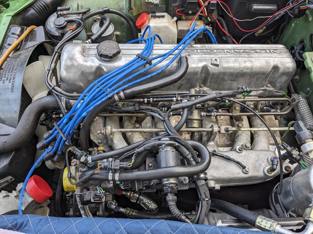
Added heat shielding for the AC lines
PXL_20230903_141756245.thumb.jpg.6f0690b8fd29a0a74d559e7847371690.jpg


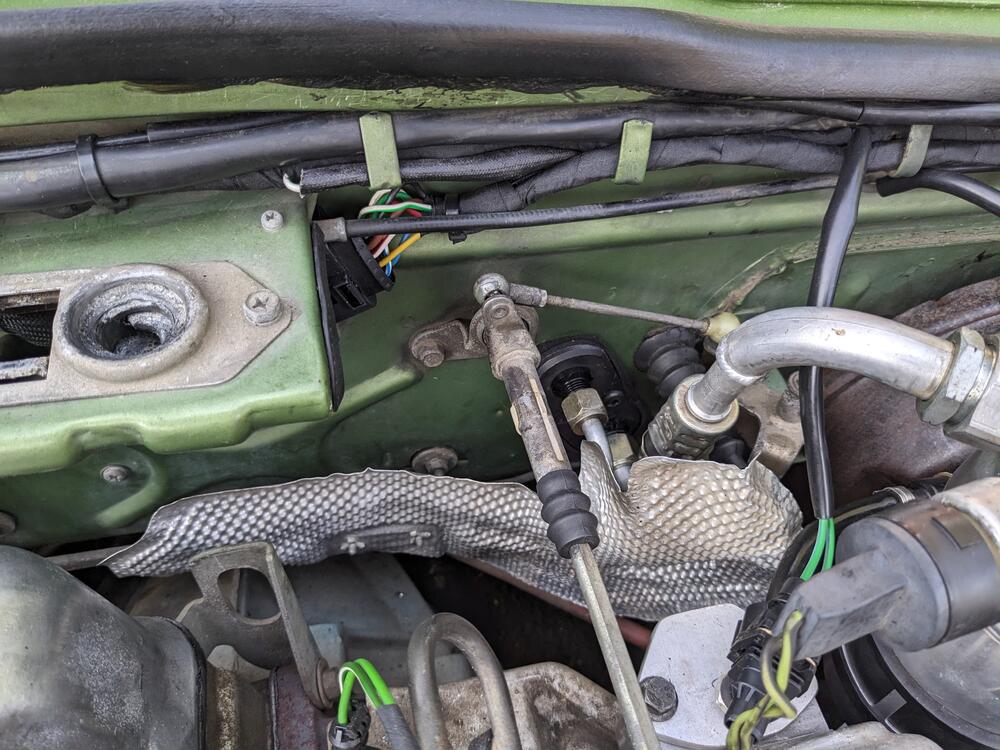
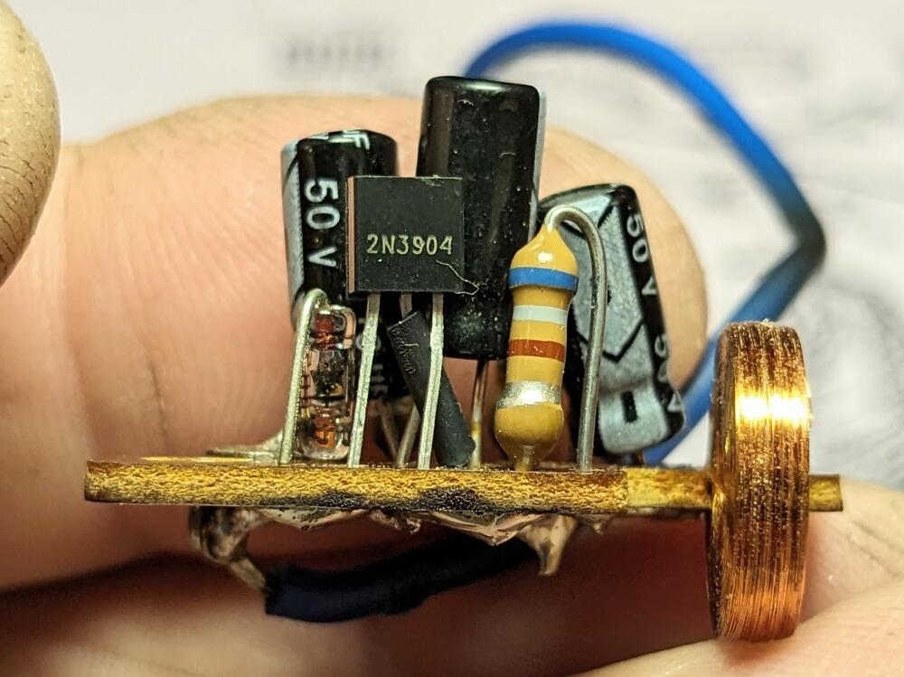
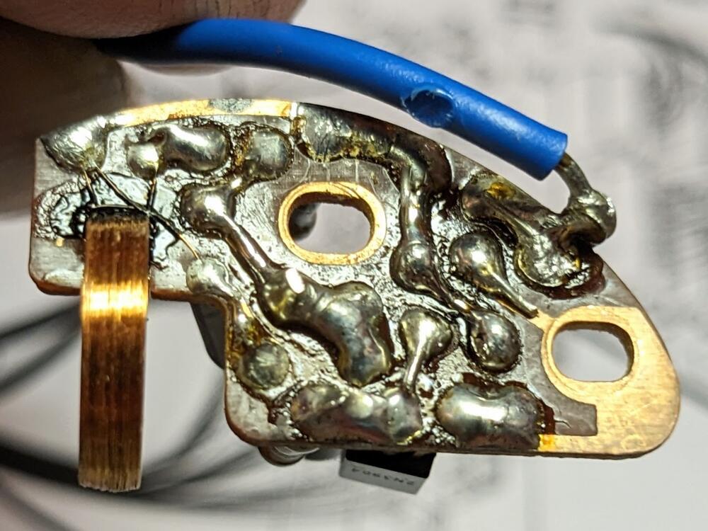
Coil (-) connection. Red-White, since that's what Volvo uses. Blue is usually (+), glad I checked what Nissan uses for (-)

PXL_20230903_145005094.jpg

Drilled (9/16") & tapped the intake for 3/8" NPT fitting

PXL_20230903_162356425.jpg

PXL_20230903_165615380.jpg

Made a support plate for the 3517886 IACV. No room for a bolt to come through the plate from above, so I welded a nut on the backside & put in a short stud to retain the IACV bracket. Re-tapped the vacuum port for the charcoal canister to 1/8" NPT & plugged it. The IACV hose passes right over it

PXL_20230903_184851942.jpg

Moved charcoal canister vacuum port to rear of plenum, using quick connect with nitrile line

PXL_20230903_184920200.jpg

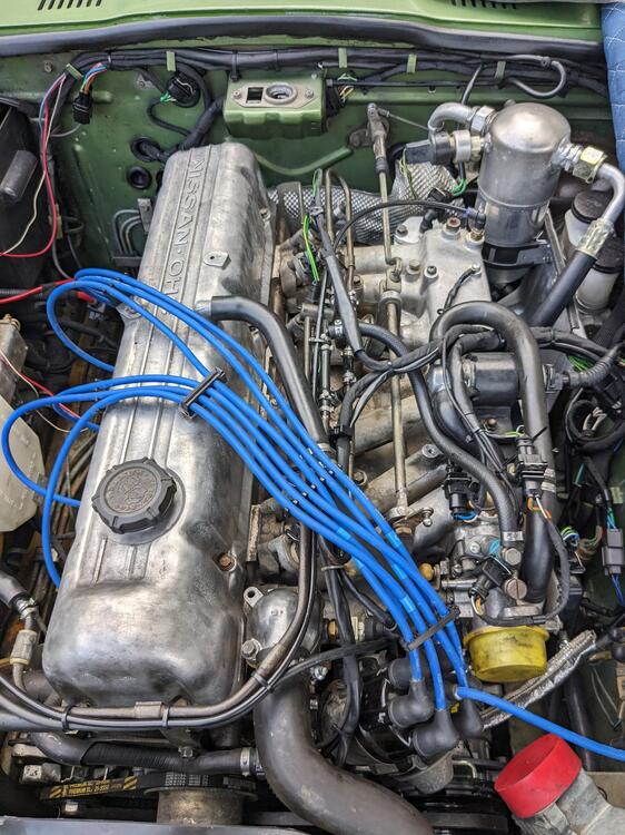
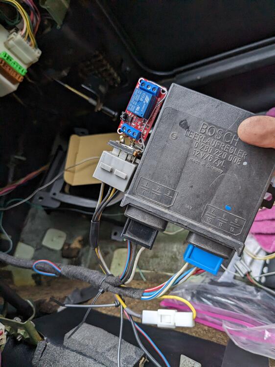
With the IACV placement sorted, I wired the 3 pole connection

PXL_20230903_194720523.jpg

and the 2 pole for the ECT, and the ground connections on intake
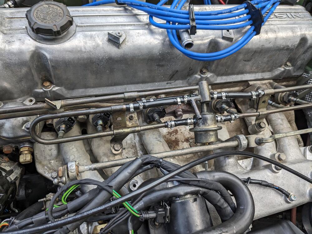
PXL_20230903_204044001.jpg

CSV placement in TB

PXL_20230903_211429721.jpg

PXL_20230903_211435342.jpg

to get a clean run on the CSV feed hose, I'm going to flip the CSV. Converting to barb fitting. I have 3 different Volvo CSV - this one has an offset connector compared to the one above

PXL_20230903_222923542.jpg

PXL_20230903_222935392.jpg

Made the block off plate for the B.C.D.D, with 3/8" NPT port for the valve cover vent. Used the B.C.D.D base gasket as the template for the mount holes

PXL_20230903_213610547.MP.jpg

shaped somewhat, brass elbow fitted. Used HondaBond to seal plate.

PXL_20230903_222032329.jpg

B.C.D.D port re-drilled to match the greater breather vent ID above

PXL_20230903_222241589.jpg

PXL_20230903_222326372.jpg

Breather vent elbow hose fitted below will clear the TPS once reinstalled. Have to figure out a clean way to unify the valve cover port hose with this

PXL_20230903_215131574.jpg

78 280Z AAV & Breather vent hose layout for ref.
PXL_20230312_191359898.thumb.jpg.39f92b99a0b668df8db57b6e1558a2ec.jpg
 
Last edited:
I have noted over time an amazing array of connector and housing types being used. As these in many cases are connectors you are adding, what drives your choice versus keeping with one family of housings with connectors?

Is it in part driven by size of housing relative to where it is being used? Connector density? Amperage it can carry?

I know many connectors are driven by the thing being attached to (sensor, switch etc).

Just curious. I appreciate the notes you leave yourself :) to follow the bread crumbs back for future serviceablility.

A lot of work for an engine which will be going away ( I know you are making the car livable in hopes someone might sit in the car with you for extended periods :) )

Have you harvested the donor and dumped the other Z carcass yet? Extended the garage?
Hello Karl
For ones I'm adding for harness junctions, vs. components that I just need to match, first considerations are anticipated load, number of terminals & whether sealed is required. Most of these are 2.3mm series AMP/TE Junior Power Timer. I also have Yazaki & Sumitomo 4.8 & 6.3mm connectors for higher load requirements.

Yeah, I don't expect to use this for more than a year, but you never know.

I haven't touched the 350Z yet, it's sitting in my Mum's driveway 😜
 
Last edited:
Back to the clock. I ordered replacement transistors, based on advice from the Datsun guy that rebuilds them (ZClocks). He provided the details on transistor variants. C828 is what was used originally. 2N3904 is readily available, so I bought a pack of 5 name brand (NTE) transistors.

ckt-bd-2.jpg.389df012fa170280e8d774db3ad6fbba.jpg


The transistor is oriented with the flat facing out, so I made a sketch to guide me, as the two legs have to be crossed
PXL_20230904_133434140.thumb.jpg.10ce3ca1a99ec6bb0b652b8324c169cd.jpg

PXL_20230904_134517518.thumb.jpg.7a35b47dcaccf5f01aa0a54f13090703.jpg


BUT..... I wasn't looking at the transistor based on the legs viewed from beneath as it states, so they are not correct here, and needless to say it didn't run

So, this is the corrected orientation
PXL_20230904_193124684.thumb.jpg.ee09c6376bc933af1b1433acea9a524b.jpg


replaced again
PXL_20230904_230756356.thumb.jpg.4a9759d920df8e3238e89353408b861e.jpg

PXL_20230904_230816461.thumb.jpg.d4546aebdb398e7edba77c0eb3a59713.jpg

Now it works! Yay!

 
Last edited:
Only had about an hour after school today, so I worked fitting the CSV to the TB, and figuring out the VC vent/breather setup to the TB

The Volvo CSV uses an o-ring to seat, rather than a gasket, so I countersunk the hole in the TB to 14mm, to allow an injector o-ring to seat snugly in there

PXL_20230905_202612451.jpg

PXL_20230905_202622635.jpg

after that I worked on the vent/breather. I couldn't see a clean way to route the hose the long way around, as the factory layout runs, so I doglegged it & I'm running it down to the inside of the TB, clear of the linkage

PXL_20230905_200710062.jpg

The thing about doing it this way, the #1 exhaust runner is exposed in that area, for whatever reason Nissan didn't make the pretty extensive heat shield come that far forwards. Since I don't want the vent hose to get crispy in the heat, I made a stainless steel additional shield, attached to the factory one. 5" length, about 2.75" deep, with a 3/4" flange

PXL_20230905_204723539.jpg

PXL_20230905_204729592.jpg

adding SS M6 rivnuts

PXL_20230905_211013290.jpg

fitted

PXL_20230905_211242660.jpg

now the breather is protected somewhat

PXL_20230905_211419877.jpg
 
Minor things after work today. Temps still in the 90's & humid - not pleasant working outside.

Made the harness extension for the CSV & bridge harness for the TPS to incorporate the signal wire to the CIS module.

PXL_20230906_195620835.jpg

PXL_20230906_193138385.jpg

Next I'll need to pull the fuel injector rail & replace all the fuel hoses. I spent an hour figuring out if I could fit the Volvo FPR pod on the right side near the filter. Not going to work with the existing layout, the angles are all too acute, it would end up stressing the fittings on the pod itself, which is plastic. I'll have to think a little more about that. The only reason I'm bothering is I'd rather rework that while I have the rail off.

PXL_20230906_224740305.jpg
 
We have thunderstorms coming in, so I worked on getting the wiring & fuel hoses done so that nothing is exposed, since I have the hood off.

Removed all the fuel hoses. The injector ones were too long - approx 2" - the rail was set such that the FPR was touching the accelerator link arm. Lots of worm clamps 😞

PXL_20230907_202328227.thumb.jpg.cf9d072c3ab8b9ed70fcf1392cf280c8.jpg


After I replaced the rail hoses with sections of 10mm ID nylon fuel tube I put the rail back in place to measure the injector hose length. I reckoned 1.75" would be more appropriate & not lift the rail

PXL_20230907_202128881.thumb.jpg.383d4c51952f54151df2b4ed5904bec9.jpg


Most everything back together, so now I just need to make a TB gasket, bolt the TB back on, wire a couple connections for the AC in the bay, remove & drain the AC compressor, refill with PAG46, then I can move on to all the wiring under the dash, then get the dash back in (eventually).

PXL_20230907_211257179.thumb.jpg.b4699107b738a1dbcf3b42c3104958ff.jpg


PXL_20230907_211408591.thumb.jpg.f53087432e2d766922d41d2d65bf9bf0.jpg
 
Since I had to add a power supply for the AC fan, I removed the battery & also replaced the negative cable with a Volvo part (2005 S40) that incorporates the body ground leg.

I had previously treated the rust on the battery tray, so I primed & painted the area while the space was clear. Note the red flanged bolt - that was used on and removed from the X1/9 at some point in time :)

PXL_20230909_180249032.jpg

PXL_20230909_180912222.jpg

I added the EMS ground to the battery terminal with a ring terminal, and got rid of the old spade connection - note - Nissan used RED (!?) for the ground here, no surprise that some people connected it to the positive battery terminal when splicing original damaged wiring ...

PXL_20230909_160616911.jpg

PXL_20230909_170059623.jpg

So, ground to engine, body & EMS

PXL_20230909_185753584.jpg

PXL_20230909_185759591.jpg

The AC fan doesn't draw anywhere near 30A (which is the lowest rating I have for the new fuse panel), so I added two legs to the fuse, and ran them into a waterproof Sumitomo TS187 connector (from Cycle Terminal) , so I have a spare accessible power supply when needed
PXL_20230909_162516845.jpg

PXL_20230909_165229937.jpg


While I was under the hood, I cleaned up the spark plug wires, I realized they were not routed properly when I compared mine to the 78 Z I took the bay pic of in the earlier post
PXL_20230909_194517054.jpg

PXL_20230909_194510376.jpg


After that I made a TB gasket & put that back in, then the thunderstorm moved in, so I had to clean up pronto

EDIT - the external throttle return spring had a sleeve of some sort inside it - it was cooked, presumably from the manifold proximity, so I'm not sure of the intent. I removed the scraps & put a section of greased nylon (8mm OD) tubing inside the spring.

PXL_20230909_193738695.jpg
 
Last edited:
Touched up the silver edging

PXL_20230823_013317388.jpg

Test fitted the compressor & mount. It will have to be raised age least an inch. Rear lower mount sits on PS rack. Stock Datsun AC belt length will be OK (13x875).

PXL_20230822_201346221.jpg

PXL_20230822_201338773.jpg

PXL_20230822_201332197.jpg

Have to figure out the best place to drill through for a harness for the AC stuff

PXL_20230821_212030575.jpg
Like your habit , you do the job has was to be do. Bravo1
 
A lot going on around that throttle body.

I see you used the nylon hose in the inline connections of the fuel rail but a rubber based hose to the injectors. I presume heat resistance concerns about the nylon?

Looking good.

Some funny choices in design by Datsun engineers at the time (like the funny choices by Fiat at the time). The red for negative is a brain twister.
 
Weather has been terrible here, so not getting much done. Did a little work on the wiring inside the cabin while it was raining

harness for transistor relay for switching the stock TPS signal to the CIS module to open at idle, ground off idle.
PXL_20230911_202355328.thumb.jpg.bcd68322af708c31c750ca517781f0e3.jpg

yellow wire is the signal from the TPS, so it needs to go to the relay first, then the switched leg goes back to the module
PXL_20230911_204021653.thumb.jpg.24e450026f3996825ba40d983d6ab39c.jpg

it will be situated alongside the module. I will need to sleeve the relay
PXL_20230911_204057235.thumb.jpg.422559bc7090c8915b48fa624ca18c67.jpg
 
A lot going on around that throttle body.

I see you used the nylon hose in the inline connections of the fuel rail but a rubber based hose to the injectors. I presume heat resistance concerns about the nylon?

Looking good.

Some funny choices in design by Datsun engineers at the time (like the funny choices by Fiat at the time). The red for negative is a brain twister.
Simpler than the decel device Nissan used to prevent excessive manifold vacuum :)

Yeah, a little too close to the manifold flange for using the nylon line for the injectors. Typically, the nylon line would be sleeved to add a protective layer, too fiddly to do that on the rail parts, since they only have a single barb, double-clamps are needed for safety, which really doesn't leave room for the protective sleeving.

I also did a small amount of wiring inside the cabin for the AC circuit - just the T/stat connections here, and routing wires for the delayed engagement relay

PXL_20230911_200654936.jpg

VO 1363449. uses a sense signal from the alternator to only engage once the alternator is charging. The white/black wire to the V/reg (F terminal on alt) should be appropriate.

PXL_20230911_205540332.jpg

Have a more compact low pressure switch that can go on the backside of the Accumulator facing the firewall, instead of the sticking out over the manifold VO 9144340

PXL_20230911_205527350.jpg

a bought a number of single pole waterproof connectors, so the bullet style will work for the D+ splice at the v/reg 6 pole connector, and at the AC compressor.

PXL_20230911_215744057.jpg
 
Last edited:
I have a question on relay design - I have 3 variants of Volvo relays - 2 have diodes, but the 3rd (in the middle), I don't know what the symbol is? A capacitor or something? The part number is no longer valid, so I'm not sure what circuitry it was used to govern. That would have likely provided a clue

PXL_20230911_205448479.jpg


PXL_20230911_205516201.jpg
 
I have a question on relay design - I have 3 variants of Volvo relays - 2 have diodes, but the 3rd (in the middle), I don't know what the symbol is? A capacitor or something? The part number is no longer valid, so I'm not sure what circuitry it was used to govern. That would have likely provided a clue

View attachment 77253

View attachment 77252
Perhaps that symbol on the green relay is some kind of representation of a resistor although I don't know why it would be there. I would expect a diode like the others. It might be worth taking a DVM to it and seeing if it is a diode (or something else??). Interesting that the orange and blue ones have their diodes in opposite directions. Are the coil potential on those reversed as well when connected?
 
Perhaps that symbol on the green relay is some kind of representation of a resistor although I don't know why it would be there. I would expect a diode like the others.
Yes, it's a resistor, and meant to prevent the spike you get when it's de-energised. Not as good as a diode, but better than nothing I guess. At least it allows coil connections in both directions whereas you need to get it correct with the diode type.
 
Perhaps that symbol on the green relay is some kind of representation of a resistor although I don't know why it would be there. I would expect a diode like the others. It might be worth taking a DVM to it and seeing if it is a diode (or something else??). Interesting that the orange and blue ones have their diodes in opposite directions. Are the coil potential on those reversed as well when connected?

Volvo specifically uses 85 as the ground side of the relay coil, so most of their relays block as shown on the blue relay
 
This wet humid weather is kicking my butt - my lower back is killing me. Not getting much done at all on the Z. All I got to after school today were a few odds & ends.

replaced the pressure switch
PXL_20230912_201014399.jpg


PXL_20230912_211955747.jpg

Wired the single pole 4.8mm connector for the compressor
PXL_20230912_202655645.jpg


Wired the bay side AC delay relay feed signal (F terminal at the voltage reg) . Added bridge off the factory wire, used the new bullet connector to connect it from there
PXL_20230912_204747245.jpg

PXL_20230912_204803582.jpg


This is the fuse/relay panel that will replace the factory glass fusebox (HELLA H84960051 + HELLA H84988001)
PXL_20230911_205553744.jpg


PXL_20230912_215611386.jpg


have to make L brackets to secure it, the supplied elbows won't work
PXL_20230912_220104040.MP.jpg


Backside of factory fuseblock. Looks very clean actually
PXL_20230912_215730464.jpg


What's puzzling with the way it's wired is that (some time ago) when I replaced the blown bottom right fuse (cat monitor), I accidentally bridged to the lower left fuse, and the starter engaged. Thankfully I didn't have car in gear at the time.
PXL_20230912_215736102.jpg


Wiring to the wiper interval that I need to adapt to the "99" VW relay
PXL_20230912_215839046.jpg


Factory relay collection
PXL_20230912_215722130.jpg
 
Last edited:
The relay diagram is somewhat confusing to deal with as a reference for what's actually there.

Ultimately, the one that is unknown is the 25230-89914 relay

Screenshot 2023-09-12 at 9.20.51 PM.png

Screenshot 2023-09-13 at 8.31.45 PM.png

The reality

top: 25230-N3000 - should be Defrost relay

top right: - Horn Relay

Left: - Interval relay

Bottom front: 25230-89914 ? Online says interval relay, diagram says AC relay, but mine didn't have factory AC

Bottom right (back): Cat hold relay (not shown)

Top middle (back): 28911-89910 Seat Belt Buzzer?

PXL_20230912_215722130.jpg

Interval relay wiring doesn't match the schematic - shows 10 connections

Screenshot 2023-09-13 at 8.25.04 PM.png


but - only 7 actual

PXL_20230912_215839046.jpg


Screenshot 2023-09-13 at 8.27.40 PM.png

Harness side plug: Bl, Gn, Bl-Y

PXL_20230913_194328726.jpg

backside, lower 28911 - 89910

PXL_20230913_194306173.jpg

harness side socket - Bl-Y, R-Wh, Blk, Blk-Y

PXL_20230913_194318258.jpg
 
Last edited:
Honestly, the main reason for me to do this is to free up space - I need to add extra relays up under the dash, and the transistor ignition module is extremely bulky.

I'm going to use a Bosch power stage heat sink as the form factor & pin locaters are identical, so it will occupy significantly less space than fitting the HEI inside the OEM box

Volvo/Bosch coil for 90's model application. Different center post connection, however I already had Kingsborne wires made when I originally converted the ignition on my X1/9, so the coil wire will work perfectly for the Z. Primary resistance value of this coil is in the ballpark suggested. Not a fan of aftermarket brand coils, so this will work for me.

It would be even easier if a Bosch power stage could be used, since they are mounted in the bay with waterproof connection.

PXL_20230913_213131265.jpg

SMP HEI Module & Bosch Heat Sink

PXL_20230913_215504316.jpg

PXL_20230913_215716894.jpg
 
This wet humid weather is kicking my butt - my lower back is killing me. Not getting much done at all on the Z. All I got to after school today were a few odds & ends.

replaced the pressure switch
View attachment 77279

View attachment 77284
Wired the single pole 4.8mm connector for the compressor
View attachment 77281

Wired the bay side AC delay relay feed signal (F terminal at the voltage reg) . Added bridge off the factory wire, used the new bullet connector to connect it from there
View attachment 77282
View attachment 77283

This is the fuse/relay panel that will replace the factory glass fusebox (HELLA H84960051 + HELLA H84988001)
View attachment 77280

View attachment 77285

have to make L brackets to secure it, the supplied elbows won't work
View attachment 77288

Backside of factory fuseblock. Looks very clean actually
View attachment 77287

What's puzzling with the way it's wired is that (some time ago) when I replaced the blown bottom right fuse (cat monitor), I accidentally bridged to the lower left fuse, and the starter engaged. Thankfully I didn't have car in gear at the time.
View attachment 77290

Wiring to the wiper interval that I need to adapt to the "99" VW relay
View attachment 77289

Factory relay collection
View attachment 77286
The Datsun fuse box was certainly nicely made and well protected. The parts look nearly new. A shame there isn’t a way to translate from the glass to a blade fuse.
 
The Datsun fuse box was certainly nicely made and well protected. The parts look nearly new. A shame there isn’t a way to translate from the glass to a blade fuse.

Indeed! Especially with 250K miles on the car!
The fuse cover is melted where something overheated before blowing, besides that, the whole thing is so clean. I'll probably start listing all these bits on eBay, since they seem to fetch decent prices.
 
Back
Top