Selling the X & Bought an 75 Datsun 280Z

Cut out the Fusebox today & wired the Hella (MTA) 16 position ATC fuse panel in

Noting the grouped inputs

PXL_20230914_193343666.jpg

I batched the fuses following the input groupings above (14 total)

3 Red (1 spare) Lighting

2 Black-white ?

3 Blue-red (1 spare) Acc (15+)

4 White-red (30)

3 White-red (30)

1 Black-yellow (50)

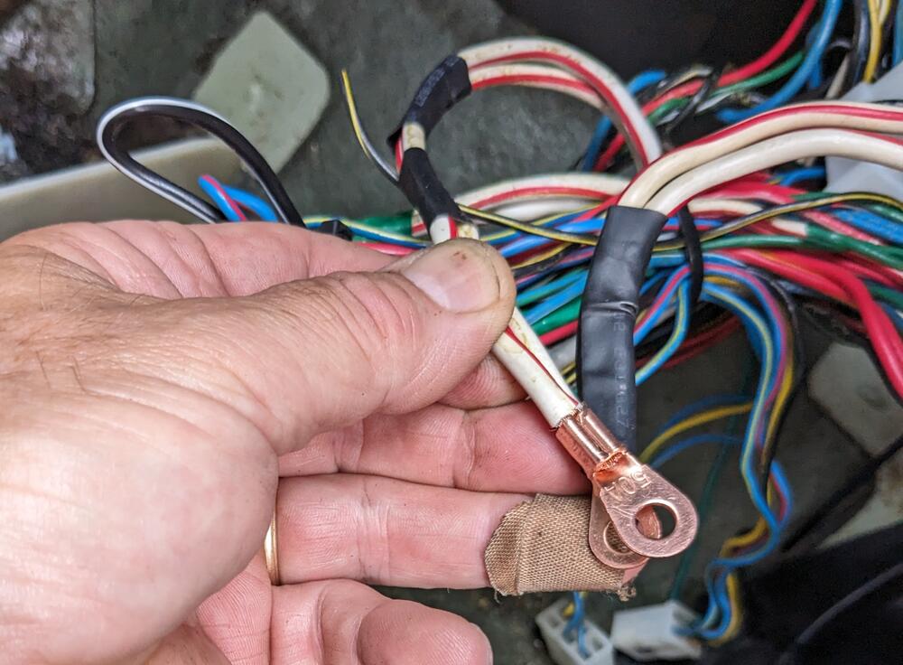
No space to batch within the fuse panel, so the splices are outside the box. Small crimp to unify individual wires

PXL_20230914_205744668.jpg

Larger crimp to join feed wires

PXL_20230914_211043218.MP.jpg

PXL_20230914_212515550.jpg

individual circuits added in decending order

PXL_20230914_213920371.jpg

separator/ pin retainer in place

PXL_20230914_215140950.MP.jpg

added spacers to the mount brackets - the door hinge bolt heads are otherwise too close to the wiring passing behind

PXL_20230914_215159609.jpg
PXL_20230914_215647762.jpg


annoying thing is that only standard cube relays will fit, not the rectangular ones I have for the AC delay & Interval, so those have to go elsewhere. The only one I need to add here right now is the relay to switch the blower on when the AC is engaged.

PXL_20230914_215557050.MP.jpg
 
Last edited:
I made a sketch with the motor & plug, the stalk & relay, so I can figure out which pins to use for the VW delay relay.

2 (yellow-green) isn't even used with the Honda motor, so it clearly has no current bearing on any operation.
original_51e23706-8225-4db2-8b88-a9e88cf31c67_PXL_20230914_175604407.jpg
 
Figured out how I will address the relay installation issue.

I made a bracket to support a row of relay sockets cut from an '80's Volvo 700 series

backside - have to be able to remove the relay socket inserts as needed

PXL_20230915_210928469.jpg

mounts using factory location of the ignition transistor module

PXL_20230915_212907296.jpg

PXL_20230915_210201135.jpg

factory trim panel works fine

PXL_20230915_213917437.jpg
 
Added more stuff, to allow for expansion when I do the V6 conversion.

Ground & power strips. Made a reinforcing plate that bolts using the stock mount points of the relay panel & ign module. Strips are riveted in place

PXL_20230916_164521628.MP.jpg

PXL_20230916_172735807.jpg

checking fit

PXL_20230916_174212852.jpg

PXL_20230916_174728497.jpg

Stripped all the CAT / floor temp circuitry out while I had this apart

PXL_20230916_194158910.jpg

PXL_20230916_210921074.jpg

PXL_20230916_204841975.jpg

added wiring for the seat heaters and WBO2 controller

PXL_20230916_210701308.jpg

Have to deal with all the wiring at the console

PXL_20230916_210706531.jpg
 
I mounted the HEI module/heat sink to a bracket I made, that attaches to the side of the stock relay bracket, where the interval relay previously lived. Made it so the assembly is unscrewed from the face, as the bracket screws are otherwise inaccessible. I'll make a sub-harness so that the module can be removed with that attached

PXL_20230916_172735807.jpg

PXL_20230916_172655652.jpg

PXL_20230916_174225453.jpg
 
Adding switched power to one relay to be used to switch the blower fan on low (1) speed when AC is engaged

PXL_20230917_211300923.jpg

Spliced the main battery feeds to run to the ancillary power strip before going to the new fusebox

PXL_20230917_203931674.thumb.jpg.d0994613e44a30ab1bec24188377827d.jpg


Going to use a Volvo fan speed resistor in place of the 3 speed non AC setup I have.

PXL_20230917_211732349.jpg

I'll modify the blower casing to fit it. Opening only has to be altered slightly. Difference is this mounts from the outside, vs the stock resistor being bolted on the inside.

Top 4 pins are speeds 1-4 next 2 pins are full speed, bottom 2 are output to blower motor

PXL_20230917_211734634.jpg

I wired the sub harness for the HEI module today

PXL_20230917_144700797.jpg

6.3mm spades for the connection to the factory harness

PXL_20230917_201625619.jpg

I made a bridge on the harness side, to connect both Blk-Wh together

PXL_20230917_144610229.jpg
 
Adding switched power to one relay to be used to switch the blower fan on low (1) speed when AC is engaged


Spliced the main battery feeds to run to the ancillary power strip before going to the new fusebox


Going to use a Volvo fan speed resistor in place of the 3 speed non AC setup I have.

PXL_20230917_211732349.jpg

I'll modify the blower casing to fit it. Opening only has to be altered slightly. Difference is this mounts from the outside, vs the stock resistor being bolted on the inside.

Top 4 pins are speeds 1-4 next 2 pins are full speed, bottom 2 are output to blower motor


I wired the sub harness for the HEI module today


6.3mm spades for the connection to the factory harness


I made a bridge on the harness side, to connect both Blk-Wh together

Your Volvo resistor reminds me of the '78 244DL I married into back in the 90s. In those cars, you had to take apart quite a few things to get to the fan resistor inside the airbox. It was mounted from the inside similar to the Datsun resistor. In fact, it was the same color green. Your upgrade to the externally installed Volvo resistor will save you or some future owner a bit of work. In the case of my 244, some clown decided they did not want to bother replacing the bad resistor in the airbox so they bypassed it and hooked up a replacement which they stuck somewhere in the center stack, I think below the radio. Since it had no air flow, it too was burned out but not before melting some plastic behind the front panel. Thus, after the repair I came away with two burned out fan resistors. Fortunately, the replacement never failed while we had the car.
 
Looking in the FSM at the AC related ducting and schematics, I see that factory AC came with blower ducts that sit under the dash

Going to have to see if anyone has added universal vents that approximate the factory supplied version. My Aftermarket setup had none, only center & dash end vents connected

items, 3, 12 & 13 are what I'm missing - I do have the "Y" elbow on the driver's side, just was blocked off. I have looked at vintage air, etc., however those vents all seem to be oversize for what I need

PXL_20230917_015424593.MP.jpg
 
Another rain-drenched day 😞

On a plus note, I have both factory under dash vents & the r/s elbow on order 🙂

I couldn't work outside, so I fitted the Volvo fan speed resistor to the blower casing. M4 rivnuts to retain it, added a little extra butyl to adjust for the folded seam Nissan used here

PXL_20230918_202113458.jpg

PXL_20230918_202701411.MP.jpg
 
Worked on the power circuits today

Organizing additional wiring, relay grounds

PXL_20230919_144214585.jpg

Wired spare relay sockets with power & ground. Only 2nd from bottom is needed right now (AC-on blower fan override)

PXL_20230919_144206015.jpg

Wiring secondary relay panel, additional 6 fuse panel, ground, 30 & 15 rails

PXL_20230919_175402440.jpg

15 rail is part of relay panel. Volvo inserted 3 rails in the relay/fuse panels. I kept this one.

PXL_20230919_145959573.jpg

making sure that everything can be removed, and has enough cable slack to move out of the way as needed

PXL_20230919_175412462.jpg

test fit again, re-wrapped harnesses, place CIS module

PXL_20230919_213902596.jpg

PXL_20230919_215059344.MP.jpg

PXL_20230919_215109549.jpg
 
Did the HEI resistor bridge today, and installed the Bosch coil

original

PXL_20230920_190722621.jpg

center post snapped off, so I riveted the spade tang to the bridge. Doesn't really matter since the coils gets full battery voltage at any of the connections

PXL_20230920_195209542.MP.jpg

PXL_20230920_211428695.jpg
pulled the compressor today, drained & flushed the Mineral oil out, added 5floz of Pag46

PXL_20230920_205257875.jpg

DS AC under dash vent arrived (EDIT, wrong part, AutoPartOne gave me a full refund)

PXL_20230920_213159180.jpg

Bought Dayco 80165 1.25" ID hose (found it suggested on another Z forum) to cut & fit for the ducts

PXL_20230920_224606337.jpg
 
Last edited:
Right side vent & elbow duct arrived today - gave them a good clean

PXL_20230921_231032051.jpg

Ran the 3 wires for the AC t/stat through the factory harness - there were 3 empty spots Dk Gn/Wh, Gn, Gn/Wh

PXL_20230921_192708595.jpg

Cleaned up & applied rust convertor to the air intake flange

PXL_20230921_210249436.jpg

extra 7 wires will go into a gang plug for future use
PXL_20230921_193723484.jpg


370Z Headers for the VQ35DE install - they come with the crappy perforated gaskets, so I got MLS ones off RockAuto. Flange has to be cut off & angled outlet added, following one install
PXL_20230921_230258050.jpg
 
Modded my blower casing today - enlarged hole carefully with die-grinder & half round file to clean it up. Went to 5.7" Kia Sportage Fan cage can be angled in place

PXL_20230922_213955648.jpg

PXL_20230922_214011430.jpg

5.75" cage OD

PXL_20230922_214027288.jpg

PXL_20230922_214047022.jpg

Put the dash frame in with harness, to check the systems
PXL_20230922_214346688.jpg
 
There is a problem with the idle control - idle rpm is way too high for any modulation. Pretty sure there is a passage from the plenum side of the TB back through to the intake via the passages used for the factory BCCD system - openings in bottom area. I thought they were closed off, but too much air is bypassing the idle valve circuit.

PXL_20230909_193738695.jpg
 
Last edited:
  • Like
Reactions: 86X
OK - so I had a break in the rain this morning, so I was able to remove the TB during one clear patch, address the ports I hadn't closed off, then get it back on during another break in the rain

PXL_20230923_140244367.jpg

Larger port I tapped with 1/8" NPT

PXL_20230923_141400870.jpg

thread sealant on plug

PXL_20230923_141819941.jpg

tapped smaller port with M5x1, used the snapped off stud from the ignition ballast to make a plug

PXL_20230923_142500410.jpg

PXL_20230923_143306329.jpg

done

PXL_20230923_143355983.jpg

Back in. Ran the motor - don't have the tach installed, however the rpm's felt much more in line. A little low perhaps, so I ran it to normal op so I could check the base setting. With CIS, the easy way to do that is close off the low vacuum tube from TB to the IACV. It stalled out, so base was too low. Opened the idle thumbscrew a couple turns (I had completely bottomed it out) & got the idle what felt around 750. Releasing the tube, the idle motor cycles & the idle rises to what feels like 850-900 range. I will set it more accurately once the tach is in, but it feels good. Motor revs freely & returns to idle.

PXL_20230923_144113762.jpg

After that, I prepped & painted the blower casing

PXL_20230923_150531593.jpg

The blower needs a cushion - I put closed cell foam on the housing first - that didn't work so I transferred it to the lip of the blower motor outer flange

PXL_20230923_160245608.jpg

The stock bolts were too long now, so I switched to shorter M5 hardware. Bolts line up with stock holes, no mod to casing required

PXL_20230923_161246657.jpg

squirrel cage offset

PXL_20230923_160952381.jpg
Flex coupling to heater box, also needed foam
PXL_20230923_172959351.MP.jpg

The duct I had bought - Dayco 80165 hose based on a Z forum thread, doesn't fit the pass vent or either of the elbows - those are all approx 1.4" OD. The DS vent is slightly smaller OD for some reason - I was able to stretch the 1.25" Dayco hose over it, but no way it's gonna fit the other positions. I've ordered some 1.5" preheater tubing (aluminum w/cardboard outer layer)

PXL_20230923_172752951.jpg
 
Last edited:
Been raining all weekend. Since I can't work outside, I got back on the clock repair.

First, I checked some of the remaining caps rated at 10uf. Most of them were 8-8.3uf (!) , others were 10.5 or higher. The .22uf caps were all under 2.1, most were .2 or below.

PXL_20230924_163038895.jpg

I removed the .22uf (read as .20) and one of the 10uf (read at 10.45) from the circuit board. The other 10uf read at 10.3, which was closer than most.

PXL_20230924_162647145.jpg

I found one .215uf and one 10.1uf cap, so I installed them.I also added 2 sockets (not in focus, sorry) to allow me to plug in various resistors if needed to adjust the resistance of the 2M resistor

PXL_20230924_181645375.jpg

Turns out, I didn't need that - with the replaced caps, the wheel was triggered & the clock runs. It's been keeping time since 2pm, so I'm hopeful that's that.

PXL_20230924_213028537.jpg
 
Test fitted the blower/duct casing to check the blower resistor connectors. Had to relieve the cowl a touch to allow the connectors to be inserted/removed. I have a4 speed switch coming, so that will govern 2-5, and 1 will be the AC-on initial speed.

PXL_20230927_193850563.jpg

(re) wiring the blower resistor - Volvo uses switched (+) to the resistor vs. Datsun's switch (-), so I'm going to change it around - primarily because I've already wired the AC-on feed as a positive input

PXL_20230927_214123024.jpg

PXL_20230927_230122172~2.jpg
 
Back
Top