Factory Engine Specifications

Below are some engine specification and output figures for the SOHC engine. I'll try and compile this in a more tabular format, but for now this will do. I have an extensive library of OE "Specifications and Features" which I'll scan a few pages and include thumbs next to each, as time permits

128 sedan

128 sedan 1100 1969 type128A.000
8.8:1 C/R
output 55hp * 6000 (din)
torque 7.9mkg*3600 (din)
12/52 52/12 camshaft
single choke 32ICEV weber
(source "Specifications and features" 128 sedan july 1969 Fiat)

I know all sedans have a single front exhaust pipe including the rally.The exception to this is 1974-only USA 128 1300 (Sedan, Wagon & Coupe) models all had a factory-supplied 4-into-2 cast iron exhaust manifold & corresponding 2-into-1 downpipe fitted to them.

128 sedan 1972 (usa specification) engine type 128A.040
8.5:1 C/R
output 52hp *6000 (din)
torque 7.5mkg*3400 (din)
10/54 54/10 camshaft
single weber 32ICA
(source "specifications and features" 128 sedan supplement USA 3/72)

128 sedan 1975 (european specification)
engine type 128A.000 (1100) / type 128A1.000 (1300)
both engines 9.2:1 C/R
output 55hp/60hp (din)
12/52 52/12 (1100cc) 20/44 60/4 (1300cc)
both engines single 32ICEV
(source "owners handbook" 128 sedan/wagon 1975 1st edition)

128 Sedan 1300 1976 (north american specification) type 128A1.040.6
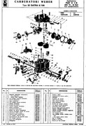
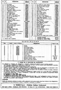
weber 32DATRA11/100 carb, non catalytic
(source "specifications and features" supplement emissions USA 6/76)

128 sedan 1300 1976 (north american specification) type 128A1.031.6
weber 32DATRA14/100, catalytic converter
(source "specifications and features" supplement emissions USA 6/76)

128 Rally 1300 1971 type128AR.000
8.9:1C/R
67hp * 6200 (din)
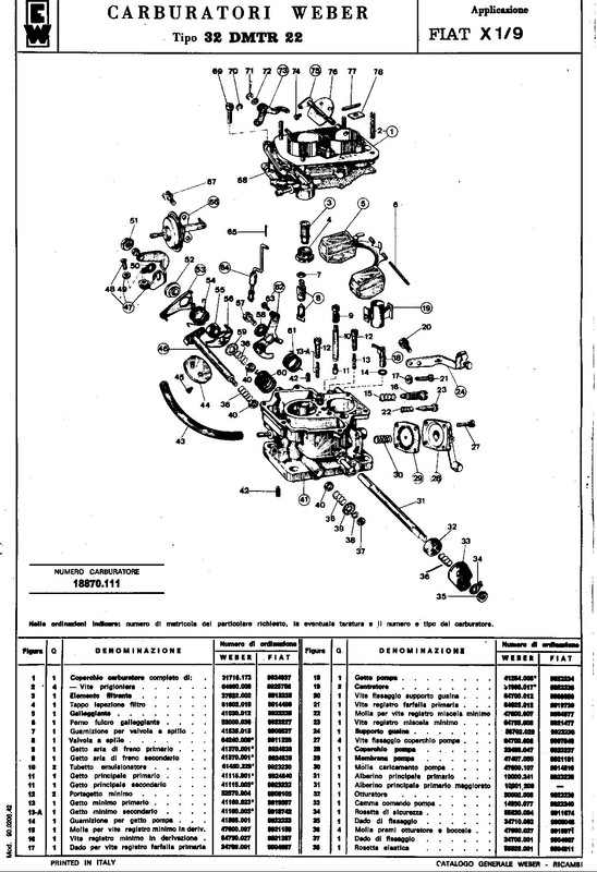
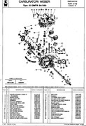
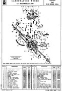
twin choke carb 32DMTR 20
Single outlet exhaust manifold
(source "Caratteristiche E Dati" Fiat 128 Rally 1/1972)

128 coupe

128 coupe 1100 1971 type 128AC5.000
8.9:1 C/R
output 64hp * 6600 (din)
8.3mkg*3800 (din)
twin choke carb
(source "All the Fiats 1984")
from my other info, twin front downpipe, 24/68 64/28 cam

128 coupe 1300 1972 type 128AC.000
8.9:1 75hp (din) *6000
9.4mkg*3600
24/68 64/28 camshaft
twin venturi weber 32DMTR 20
(source "specifications and features" 128 sport coupe 1st revision 11/72)

128 coupe 1300 1972 U.S.A. version type 128A1.040
8.5:1 C/R
output 51hp*5600 (sae)
torque 8.5mkg *3000 (sae)
10/54 54/10 camshaft, single weber 32ICA
(source "specifications and features" 128 sport coupe 1st revision 11/72 U.S.A supplement)(dont ask me why some figures are quoted as S.A.E. because I dont know, it could just be for the US market, maybe that is the standard there?)

128 3P

128 coupe 3P 1100 1975 type 128AC5.000 (?)
9.2:1 C/R
output 65hp (din) (up 1 hp fron prev)
torque 8.9mkg*4100 (din)(up from 8.3mkg * 3800)
twin choke carb
(source "All the Fiats1984")

128 coupe 3P 1300 1975 type 128AC.000
9.2:1 C/R
output 73hp (din) (down 2hp from 75)
torque 10.2mkg*3900 (din)(up from 9.4mkg*3600)
twin venturi weber 32DMTR/??
(source "All the Fiats 1984")

128 coupe 3P 1300 1978 (aust specification) type128AC.023
9.2:1C/R
12/52 52/12 camshaft
32DMTR/32 carb, has emmision control gear on it (fuel vapour recirculation)
the inlet manifold has much smaller inlet ports, it quotes 73hp (din) (but I dont think so...like the inlet manifolds supplied to USA 3P's)
(source "owners handbook" 128 3P )

128 3P (North American version)
type 128A1.040.5 non catalytic (1975)
type 128A1.040.6 non catalytic (1976)
type 128A1.031.6 catalytic (1976)
8.5:1 C/R
output 62hp *6000 (sae)
torque 9.3mkg*4000 (sae)
10/54 54/10 camshaft
twin choke weber 32DATRA1/100 non catalyst ' 75
twin choke weber 32DATRA11/100 non catalyst ' 76
twin choke weber 32 DATRA14/100 catalyst ' 76
(source "owners handbook" 128 3P US version 1976)

X19's

X19 1300 1972 type 128AS.000
8.9:1 C/R
75hp * 6000 (din)
(source "All the Fiats 1984")
from my info, twin choke carb, twin front pipe,24/68 64/28 cam in europe

X19 1300 1977 (australian specifications) type 128AS.023
9.2:1 C/R
12/52 52 12 camshaft
5 degrees static ignition and 28 degrees + - 2 of centrifugal
single front pipe, no catalytic, but the system as per catalytic with just a test pipe fitted, weber 32 DATRA 19/100
(source "owner handbook" X19 9/77 3rd edition)
I can confirm all of this too, as i've dialed the standard camshafts, and cc'ed the standard chambers, standard output unknown, quoted as 73hp (din) (din_think_so :shock: )

X19 1300 (usa specifications) type 128AS.031.5 non catalytic
type 128AS.031.6 catalytic
8.5:1 C/R
output 61.5hp *5800 (sae) (C.C. cars 61hp)
torque 9.3mkg*4000 (sae)
10/54 54/10 camshaft
32DATRA (various) carburettor
(source 'specifications and features" X19 (us model) 1977)

X19 1978 (five speed) type 138AS.000
9.2:1
output 85hp (din)
torque 12mkg*3200 (din)
twin choke carb (listed as 34DATR 7/250)
(source "All the Fiats 1984")
these definitely have the twin front downpipe, non catalytic, camshaft is 24/68 64/28 in europe)

X19 1981 (US specifications) type 138BS.031
8.5:1 C/R
output 75hp *5500 (sae)
torque 79.6ft/lbs *3000 (sae)
bosch L jetronic, catalytic convertor
(source "specifications and features" X19 supplement fuel injection 10/81)

X19 1982 (carburettor) 1500 (australian specification) type 138AS.023
9.2:1 C/R
output 80hp*5750 (din)
torque 12kgm*3250 (din)
10/54 54/10 camshaft
twin choke carb 32DATRA 23
(source "owners handbook" X19 Five speed 1980 1st edition, supplied with my 1500 5 speed X19, and once again I can confirm all this as I have verified the original cam specs)

Ritmo/Strada

Ritmo / Strada
60hp / 65hp / 70hp
1116 / 1301 / 1498
9.2:1 / 9.1:1 / 9.1:1
8.3mkg*3500/10mkg*3500/12mkg*3000
these use single choke carburettors 32ICEV 1100/1300 34ICEV 1500
(source "All the Fiats 1984")
 
Last edited:
F.I.A. Specifications

X19 Chassis Specifications.


128 Rally Chassis Specifications


X1/9 group 3 F.I.A.homologation Documents (3082)
Found this information online, not the highest resolution. When I get a chance I will scan my copy for clearer images.


Last edited by a moderator:
Weber factory jetting tables and scans

A selection of scans from my Weber 'bible' of some of the most popular factory installed carburettors and carburettor upgrades.

This is just a start, there will be more scanned as I have time.

32DATRA and derivatives

32DATRA 8/100


32DATRA 8/200


32DATRA 10/100


32DATRA 10/200


32DATRA 19/100


32DATRA 100


32DMTR and derivatives

32DMTR 22


32DMTR 34/250


32DMTRA 1/200


34DATR and derivatives

34DATR 2/250


34DATR 4/200


34DATR 4/250


34DATRA 15/100


34DMTR and derivatives

34DMTR 21


34DMTR 21/200
 
Last edited by a moderator:
The R.P.F.C.C. blog (Started July 2016, edits and additions as dated)

Introduction.

What started this whole idea...
The Fiat Nationals. This is usually a three day event held on the east coast of Australia at a motor racing circuit, where you get to take your club car or road car onto the track and enjoy yourself. Sure there are bragging rights for F.T.D, but as everyone is in different cars it was always a difficult task to rate drivers.

Here in Australia on the Turbo 124 forum, the idea was hatched for a cheap reliable car that could be run by allcomers on the day at our annual Fiat Fest, with the idea being similar to a 'Top Gear' star in a reasonably priced car... and the 'Reasonably Priced Fiat Challenge' was born.

A Fiat 132 with cage already fitted was donated by a member in the West, another member worked for a freight company and arranged to have it trucked across the continent, others donated parts, and Ross Smith from Fiatorque took on the task of preparing the car so it would run reliably throughout the day, with 30 entrants all doing three laps (1/2 lap out, 2 timed sprint laps, and a 1/2 lap in) so the car was going to be thrashed for close to 100 laps in a day. It performed brilliantly and has become a regular feature of the nationals track day. It lasted for a few years, several years later was replaced by a turbo diesel Fiat Punto S, but that has also recently (2017) been retired.

My very similar idea was hatched just a few weeks ago. I've taken my nephews go karting at our local race track twice in the last 3 months. You get to hire twin engined race go karts and compete in a 'Mini Grand Prix' against all comers on the day. We picked the late session (twilight) on Saturday afternoons when the weather looked bad... These karts don't really have a lot of power, they are twin Honda stationary engines that rate around 12Hp each, but in the wet horsepower doesn't matter (or weight so much as they both weigh 15/20kg less than I do) and it evens out the field based on your driving skills. I ended up winning the meet outright both times in the wet, with my nephews pushing me hard all evening ... I've got a few years of race-craft on them, but they are definitely getting the idea of vehicle control on a slick surface.

After the most recent outing, we sat around eating pizza's and having a couple of brews, and I put forward the idea of building a club car to compete in. Not wheel to wheel racing, but solo timed events, sprint days, time attack, hill climbs and the like. We could probably get one outing a month if we planned a years schedule, and I pointed out for similar money that we spend on an evenings karting, if we all pitched in we could race a 'real' car.

Both they (Anthony and John) and their Dad (John Snr) as well as a couple of friends who had joined us all liked the idea... so the 'Reasonably Priced Fiat Club Car' was born. To start with it won't be about ultimate speed, more bragging rights among us. John Snr is also keen on having a go and has the trailer and support vehicle to get the X19 where it needs to go. The boys agreed to help and buy a few items like the race seat and a harness. For the club events we plan doing a rollcage isn't mandatory, so this keeps the build cost right down.

Back in 2013 I purchased a 1978 series 1 X19, complete and running, bodywork OK, 1300 4 speed. Very tired interior. CD58's in poor cosmetic condition. The outside is all white, bumpers, trims, just about everything. No grille (has mesh fitted) but it's in generally sound condition. One really good thing is that it's had the steel water pipes replaced. This coming weekend the boys are heading up to my place and we are going to begin the build. Anthony has borrowed a fender lip rolling tool and the first task will be to fit the wheels (and some dummy tyres) onto the car... afterall a race car is built around the tyres.

The car as it was purchased August 2013.
series 1 x19 pic1.jpg

series 1 x19 pic2.jpg


The plan is to step by step go thru the performance modifications. It's good information for my book (which this 'ultimate SOHC thread is the working draft) and it will give my nephews a good grounding on what works and why.

Added August 2019:
Well as sometimes happens life takes a sideways step and the project stalled for a while, but is now back on track with a slight change in focus. Instead of a trailer to the track type of car, which can be a bit of a pain at times, I decided this while project would make more sense and be a better test-bed if it were road registered. This means a build in a couple of stages, as having the car registered means having to do without certain modifications for it's roadworthy inspection. It's mainly the brakes, as replacing the pedal box / master cylinders and mounting different calipers would require full engineering if used on the road, so for now I'll be going with upgrades that are 100% road legal.

Chapter one. Engine
First up is a 1500 with some 34.9ch flat top small flycut pistons (about 10.25:1) with stock (ported and prepped) head, standard valve sizes, one of my 36dcnva sets on a 1500 euro manifold, a euro cam and a stock twin out exhaust manifold mated to the stock muffler... it gives me a running driving car to tune and dyno test for some real world numbers ...I'm hoping it will push around 90 to 95 at the wheels. Not too powerful so the boys can learn to drive the chassis to it's limit. That's going to be the first chapter in this section. I'll get out to the shed and take a bunch of pics of the parts I've compiled and take step by step pics of the engine build as I go along.

Added August 2019:
Engine build plan has be finalised.

fiatfactory said:
I also found another core engine... this one is from an 5 speed x19 too.
I figured with several sets of pistons I would be able to build two engines
(it's always nice to have a spare)
This one cost me $450 as a complete engine but the head was already removed.
(with manifolds but no carb and no ignition)

1382core.jpg

1382core1.jpg

It turned out that the guy selling had bought the engine (for $500) used from an X19 owner
who was going to do an (MR2 - 4AGE) engine conversion. So he bought it to use in a 128 project,
but he had lost interest when the panel beater told him how much the rust repairs were worth on his 128 coupe!!
He told me that the engine came with recipts for work done,
and blow me down if the guy doesn't produce a "Fiat Factory" invoice from back in 1995!!
I didn't let on... :) ... and prodded and poked, and talked the guy down from $500.

When I got home I did a little searching and you guessed it,
I had built the engine, but it was for the same car I am now turning into a 2B racer...
almost karmic isnt it, the engine and chassis reunited after being separated many years before!

This engine has 86.8 Kolben Schmidt 0078003 (86.8mm) pistons and a 40/80 pittatore cam... :D
and had done a mere 6000km before the gearbox broke and the previous owner removed it from the car.

I've taken this engine to use as core for the RPFCC 's first engine, it's a basic build, with reliability and a strong flat torque curve in mind. 86.8mm bore x 63.9 stroke.

I've removed the 86.8 K/S 34.7CH pistons and they are in almost perfect condition, so a new set of rings is all they need. The stock 1500 forged rods and new rod bolts / nuts can get recycled into another engine, for this build I'm using Ross lightweight gudgeon pins, and a set of Scat rods.

I sold the original core engine's cylinder head, as it had the air injection port, not that this really affects performance as the effect on the exhaust port flow is minimal, but I had a better core to start with. The cylinder head for this build started as a very good condition used late 1300 head which I fitted 8 new valve seats and 8 new bronze valve guides. It has been fitted with 37.5 / 33.4 valve sizes and the seat throats are 34 inlet and 28.5 exhaust. The intake ports have been enlarged and the valve guides have been trimmed flush with the port roof, the exhaust port has only had bowl and turn work the guide has been left full length but narrowed

I'm going to use one of the 1300 euro inlet manifolds that I have modified by my friend Sergio, as it give me more material to do the match port with due to it's smaller port size, more work but a better match up in the end. Stock 4/2 exhaust manifold, custom exhaust.

An emphasis on lightweight components and an overall light weight reciprocating package is going to be a bit of a focus.

Chapter two. lightweighting the car and a bit of bodywork.
Luckily I have good fibre glassing skills. I've layed up moulds and panels for quite a few race and rally cars over the years. It's a skill I was taught when I was a young teenager and like riding a bike, it's something that you just don't forget. Again I can run through this step by step, and hopefully I'll explain myself well enough that others out there who have similar plans can tackle the job with confidence. A lot of extra speed can be found with Colin Chapman's addage of 'Add lightness' as it helps with acceleration, braking and cornering, so for me this is a very important step of race car preparation.

Added August 2019:
First up the car has been completely stripped. Then I've scraped and chipped away every single scrap of sound deadening / seam sealer / under-seal on the body. I also stripped the outside panels back to bare metal, as the white paint had been applied quite poorly.

20190729_171057.jpg


Fibreglass panel fabrication.

The first stage of mould making, and also when you make the panel from a mould, is to wax the surface with "Mould Release Wax". Don't do too much area at once, or the wax will dry out and ridge up and ruin your surface finish. Rub on a good amount of wax with one cloth over a small area and rub it in well. Wait a couple of minutes, then with another soft cloth, buff the wax off to a good shine. Make sure the whole panel/mould is thoroughly waxed.

Doing this and the next stage is to ensure that the mould and panel come apart easily.

The second stage is to apply a "release agent" to the mould surface. This is a sticky liquid that is spread thinly over the surface, and when it dries, can peel off and is a bit like plastic cling food wrap. It's water soluble, so cleaning it up is simple. I prefer to apply this on with a spray gun, though it can be sponged on carefully, but you have to avoid any streaks or runs, as they will show up in the mould. Low air pressure for spraying it on works well, and the release agent won't mist up as much with lower working pressure at the gun. Wear a spray mask, I doubt the stuff would be great for you to breath in. Let it dry completely before progressing to the next stage.

To give a hard surface on a mould that will withstand multiple uses it is best to use some sort of gelcoat. Gelcoat is a bit like resin, but it is a lot thicker in consistancy, and gives a harder surface finish than just using resin for the "topcoat". You mix up gelcoat pretty much the same as resin, by adding in a measured amount of MEKP (Methyl Ethyl Keytone Peroxide which is a hardening agent, often called a "catalyst") and mixing it in very well. A cheap gelcoat substitute, and an effective way of making resin thicker is to mix Talc with it, you need to mix up very thoroughly and do this before adding the catalyst.

I use old ice cream plastic containers to mix up resin / gelcoat, they are a convenient size, and reuseable as once a mix dries completely, the remaining resin/gelcoat cracks out of the plastic container easily. I weigh things out on an old set of kitchen scales to determine the amount of catalyst to add to a batch.

Depending on the ratio of hardener to gelcoat used (and the ambient temperature) the gelcoat has a workable timeframe before it begins to harden. Spread the gelcoat over the surface to be moulded evenly with a brush. When the gelcoat reaches a certain point during hardening, it becomes quite rubbery. At this stage any drips and lumps around the edges of the mould/panel should be trimmed of with a sharp utility knife. If the gelcoat has hardened too much, it will tend to tear, so be careful at this stage and time it right.

I purchased a 4litre tin of white brushable gelcoat to do this job with, which was about $60aud, so around $15/Litre. I made bonnet/boot (or hood/trunk) skin moulds, and door skin moulds for the two flat topped doors, and a late 79on engine cover mould.

To ensure that there are no air bubbles in the mould/panel we are making. A small ribbed metal roller is used to get any small bubbles out from the fibreglass layers when the resin is still wet. Once again, the resin will reach a point where it becomes rubbery, and the excess tissue or mat and resin can be easily trimmed off with a utility knife. This makes the job a whole lot easier, as grinding or cutting fibreglass when it has fully hardened is very difficult.

I have used 100GSM (grams/square m) tissue to make these moulds and panels, which costs about $1.50 per meter. For the moulds I use two layers of 100gsm tissue all over the gelcoat layer. This is followed by two layers of 600GSM chopped strand mat (about $6.50aud/M). I then apply a third layer of 600GSM, but over the top of strengthening ribs. I use rolled up newspaper, taped up and held down in place with masking tape. Its not the paper that has any strength, its the humps formed in the third (usually quite thick) layer of fibreglass mat and resin laid over the top.

When the resin has fully cured, I run a sanding block with 80grit paper around all the outer edges of the mould/panel which are still stuck together. This helps the edges seperate cleanly from one another with just a little persuasion. Coming cleanly off the door, the mould looks like this (after washing the dry film of release agent off)

I'm looking at making a mould of the inner reinforcing also for the bonnet and boot , so that I can make bonnets and boot lids that look and hinge/lock just like the original. I would like the RPFCC to have bonnet and boot that hinges and locks like an original item, but we shall see how that goes.

Pics coming soon

Chapter three will be chassis and suspension.
To start a lot will be left very stock and untouched, but camber plates, different dampers, springs, adjustable spring platforms and lots of adjustability will be built into the car as the boys skills progress. It will include setup, set down and some chassis tuning techniques.

Chapter four will be the braking system. This is something I'm going to tackle straight away, as so much time can be made up on the track with really good brakes. Simple modifications to start with, but as the engine and chassis performance improves, so will the braking system, so hopefully this will cater to everything from mildly prepped street driven cars, all the way to slick tyred racers.

Chapter five will deal with electrical preparation. Installation of the battery isolation switch (required by most motorsport sanctioning bodies) and rewiring the car will be one of the first major jobs.

Chapter six will be most other things like choosing good quality components, best practice for ancillary systems, basically the nuts and bolts of building a successful and reliable club racer.
 
Last edited:
1600 test case.

First dyno run May 2018.

1603cc engine I've just taken to the dyno for it's first tuning session

marks dyno session may 2018.jpg


Only a few pulls as initially we had a serious lean issue above 4500rpm due to insufficient fuel delivery, so we changed the fuel pump to one with approx 82 litre/hour capacity at 4psi and this solved the fuel delivery problem , car runs a return line, and I have a "redline" style inline fuel pressure regulator to install...but would prefer a "filter king" style filter/reg assembly.

At the moment running the stock Marelli S135 (non vacuum advance) distributor body with a pertronix optical trigger kit. Static set at 10 degrees, mechanical advance is about 28 degrees from memory, so total advance will be 38 and as per stock is all in at about 3500rpm or so... that's one of the things we are going to change. There's another model of Marelli S135xx distributor that uses a 22 degree mechanical advance plate, and we will try the timing at around 15 degrees static...as the low revs response could be improved a little.

These runs were with 32mm venturis, and given the power curve flattens (but doesn't fall away) from about 5600rpm, I think it could use some more air flow, so next are some 34 or 36 venturis I have to try. We also have the 42/44 style bellmouths to fit which will also help with air entry and improve things. On the dyno we had 20 degree ambient temps, but inlet air was 40 degrees, so there could be a decent gain with a cold air box ... but we just ran out of time to try all these things ... the fuel pump not keeping up and the A/F ratio spiking to the 16's above 4k rpm were more important fixes for this first dyno session. the engine is also only just 1000km old, and I built it quite tight, so as it gets more miles and loosens and beds in, power should increase again...

We started with 125 main jets / 220 air correctors, and it was immediately obvious that the engine was needing more fuel. In went some 135's and things improved but the A/F still leaned out around 6k. In went 145's and the A/F was more acceptable all the way to 7500.

But the A/F graph still looks like hilly terrain above 4500rpm too, so there is some sort of air flow harmonic/pulsing going on... as I think the air speed thru the small 32 venturis is very high. Overall happy with the result, and the engine pulls very quickly from 4k to 6500rpm in it's current setup, good enough for the owner ( Mark ) to run up another 1000km before we have another series of dyno pulls.

overall quite happy with the results, I think there's another 20hp at the wheels with this engine once sorted.

Second dyno run November 2018.
In the interim the car has done another 1500km or so, so now has about 2500km under it's belt. Several small changes to the fueling system have been completed prior to the dyno session, including the installation of an EFI style fuel tank with the bottom pickups, and the installation of a Malpassi fuel pressure regulator/filter assembly.

Dyno sheet from a couple of runs to show the difference a small change can make.

First runs (101 wheel HP and 113lb/ft of torque) from may 2018 were with 32 chokes and no bellmouths fitted. (plain cast in carb top)

Second runs (109 wheel Hp and 120 lb/ft torque) was no tuning changes apart from 34 chokes and bellmouths fitted (raised stack on stock 40DCNF carb top machined off flat)

second runs were on a much hotter day with 36C ambient temps (about 24C on the first day) and 55C inlet air temps... so there is definitely more to be gained with a cold air box setup

dyno sheet torque (002).jpg

1600 dyno day.jpeg

marks 1600 before install.jpg


Observations and thoughts...
Just because one engine responds this way doesn't mean all engines would respond the same. In some cases the installation of larger venturis could slow the airspeed enough to reduce the effectiveness of fuel atomisation, or lose lots off the bottom to gain a little right at the top of the rev range...you have to be careful and not oversimplfy the data available. It was a change of venturi size AND installation of bellmouths that led to an approx 8% increase in HP and Torque.

This particular engine was built (on paper) to get around 120/125hp at the wheels and approx 135lb/ft of torque using a computer simulation programme, that simulation was using 40mm throated carbs with 36mm venturis fitted and using inputs of known port flow figures...The real world dyno runs are for gathering information and plotting the relative results of 32/34 and soon 36 venturis and a few other tuning changes.

This time around we only did a few runs, as the ambient temps were quite high...and even with a larger venturi the A/F was showing a richer mix than it did with the 32's. This was initially a little confusing, as I was expecting to need to fit slightly larger main jets to compensate for the increased available airflow. In the end I didn't lean the jetting off as I figured the quite steady 12:1 to 13:1 AF I was seeing right thru the rev range was due to the high ambient temps (less dense air) and I don't want to risk the engine going lean when the weather cools off and the air becomes more dense.

I think what's holding this engine back now is the exhaust system, next runs on the dyno I will have a gauge hooked up to the muffler inlet to measure exhaust back pressure, and I'll try swapping in the 36 venturis I have, but I'll wait until the weather cools off around march/april next year.
 
Last edited:
Lots of the pictures in the early part of this thread were hosted in postimg.org, which seems to be on its way out. Xweb member tonyism7 mentioned in another thread that the pictures can still be viewed if you do some editing of the web address. See his post over in the other thread. Using this method, I suppose I could recreate the links, or better yet, download the images from postimg and upload them to Xweb V3, then clean up all the old links. That is a pants load of work I really don't want to commit to completing.
 
Agreed. Any idea how reliable the referenced method of changing the web address is? Especially over time? Will that change as the hosting site vanishes? Also, do we know what proportion of the missing images can be restored this way? I simply do not know enough about this technology to realize the answers.

Steve's work is already very compromised by a ton of missing pictures. It is an excellent compilation of experience and therefore an amazing resource. He offers a LOT of good information, but in many places I have a difficult time following it without images to support what is being described. Often I'm left with more questions than answers due to not being able to fully know exactly what was said. Not sure if some of the problem might be language related (Australian english vs American english), or the level of written detail included in the text (authorship related), or perhaps my inability to keep up with it, but several sections leave me wanting much more explanation (maybe I'm alone in this?). In the past I've attempted to get more clarity from the author, but with mixed results (again, not faulting him as I know there are other issues at play). Ideally it would be wonderful if the entire work could be revised/rewritten, with more images added and clearer detail in places. That would be a HUGE undertaking, but I think it would result in a publishable book. Restoring the existing images would be the next best thing. But I realize even that would be a very large task.
 
Agreed. Any idea how reliable the referenced method of changing the web address is? Especially over time? Will that change as the hosting site vanishes?

Changing the links will only work for as long as the posting server allows access. Much like Photobucket or any other web hosting service. So that method is only a bandaid. Maybe Steve will come back someday and fix the thread up?
 
Should be straight forward enough if you have editing rights to the post, cut n paste it in to an editor, save it to create a backup, do a find and replace on postimg.org changing it to postimg.cc and copy n paste it back into the post
 
Last edited:
I wanted the section on porting so last night spent about 30 minutes to view the photos using the .org to .cc method, and downloaded 30 photos to my computer.
Then printed the post to a pdf.
Wasn't bad at all.
It will take an hour more to put the photos into the pdf.
 
Should be straight forward enough if you have editing rights to the post, cut n paste it in to an editor, save it to create a backup, do a find and replace on postimg.org changing it to postimg.cc and copy n paste it back into the post
If Steve ever comes back we can talk to him about it, but honestly I would not expect him to redo all of his work. So in the meantime I don't see why we can't work on trying to restore it. Afterall, isn't a public forum open to sharing everything - as in there aren't any 'rights' to protect? (I'm honestly asking because I'm not sure, but that is my understanding).

Hopefully this does not sound like I'm really stupid (which I am but hate showing it), but I'm not very skilled at doing all the cut/paste, PDF, photo file conversion, etc, type stuff you guys are talking about. I pretty much follow the principle but lack some of the tools (e.g. don't seem to have PDF software) and the skills to pull this off - at least not in this lifetime. Therefore if anyone is able and willing to do some of it and share it with the rest of us, it will be greatly appreciated and I'll make sure you get lots of karma credits. ;)
 
If Steve had no problem with it, a third party could make a complete copy of his guide. He has been communicating on MIRA so he is still around.
 
editing rights
Oh, I think you are referring to being able to "edit" it due to the forum's structure not allowing others to modify someone else's post? Or are you meaning more along the concept of "copyright" permission from Steve?

If it is the first, would "editing" be necessary? I honestly don't know how all this technology works; could the whole document be copied elsewhere like Carl suggests, then the pics and other corrections done? Perhaps like the 'PDF' thing some have already done to certain sections of it? After which the entire thing could either be reposted by the new person, or better yet added to the forum (say in the Wiki) as a link to a PDF hosting site (if there is such a thing)?
 
I think the best approach would be to capture the thread, add the pictures, generate a pdf file and save it to the X1/9 wiki (which Jeff has already suggested).
 
Oh, I think you are referring to being able to "edit" it due to the forum's structure not allowing others to modify someone else's post? Or are you meaning more along the concept of "copyright" permission from Steve?

If it is the first, would "editing" be necessary? I honestly don't know how all this technology works; could the whole document be copied elsewhere like Carl suggests, then the pics and other corrections done? Perhaps like the 'PDF' thing some have already done to certain sections of it? After which the entire thing could either be reposted by the new person, or better yet added to the forum (say in the Wiki) as a link to a PDF hosting site (if there is such a thing)?

Admin/Access rights to edit the original post, the moderators have the ability.

The post will have image tags embedded in it (without the leading space) IE:

[ img]https://i.postimg.cc/ydjBwb7Z/32dmtr-22-page-1.jpg[/img][/URL]

Copied as plain text into a text editor a search and replace on .org can be performed to change it to .cc

The whole post can then be copied into the original post and the images will appear.

 
OK guys, I did what I could to get the postimg pictures back. Not all of them appear to exist anymore, but things are much better in the bulk of this thread. That was fun.

Just FYI, I could not find any way to make the dead Imageshack links work. Imageshack offered me 4 different link examples to replace the dead link, but none of their suggested links produced the picture. As with all Imageshack images these days, some are alive and some are not.
 
Last edited:
I did what I could to get the postimg pictures back.
Holly crap Jimbo, that is amazing work. Thank you very much. I honestly did not think it could happen. And appears that you were able to recover most of them. This is a good article but it suffered without the images to illustrate everything. Now it is back. You're my hero!
 
Interesting. I printed the 2 existing pages to PDF files in an attempt to save what exisits today. I was surprised that the links to postimg work inside the PDF. I hope that doesn't mean the PDF can end up pictureless if postimg goes the way of Photobucket. I will need to see what the PDFs look like if I disconnect my PC from my network.

For now, I have attached the PDFs for storage here on Xweb.


UPDATE: I pulled the plug on my ethernet connection to test the PDFs saved locally on my PC. The small pictures still appear in the PDF, but the links to the larger copies of the pictures on postimg fail. So that is good news, it appears if you download a copy of the PDFs, you will see the thread content as it was when I created the file.
 

Attachments

  • Ultimate SOHC engine. _ Page 2 _ XWeb Forums v3.pdf
    2.6 MB · Views: 422
  • Ultimate SOHC engine. _ Page 1 _ XWeb Forums v3.pdf
    6.1 MB · Views: 311
Last edited:
Even better. I just saved the PDF. Can you describe a pic that didn't recover previously but did on your copy of the PDF? I'll look to see if it shows on my copy (if that is of any value).

I was wondering how safe the recovered pics were. Are the ones that show in the thread now saved on the Xweb server - preserved for all time?

Thanks again Jimmy.
 
Back
Top