
You are using an out of date browser. It may not display this or other websites correctly.
You should upgrade or use an alternative browser.
You should upgrade or use an alternative browser.
Variable (delay) sweep wiper mod (1HM 955 531A)
- Thread starter lookforjoe
- Start date
lookforjoe
True Classic
The black wire with an arrow head just means take it to ground. Do you want to just insert the 99 relay or do you want to add the two current relief relays as well? I have diagrams for both that I'm happy to walk you through.
Hello Rachel - thank you - I'm just inserting the 99 relay, I did the power supply bypass mod years ago.
So, basically, I need to
add:
1) gn-bk from stalk output (red connector) for the washer pump trigger to T
2) switched power to 15 (orn) (move/use yellow wire?)
3) gy to 53s. or 53m
4) add gy to whichever isn't attached in step 3
5) add ground to 31
6) attach R to I
Existing wires at relay
r = (+)
gy = (int) [to motor, or from switch, not clear]
y = (-) ?
bl-wh = F (whatever that is)
connections at wipe/wash control
Last edited:
Dr.Jeff
True Classic
I'll have to look closer at this, but I suspect you are correct about it being similar to the VW item. Interesting info, thanks for posting it.You might also want to look at the kit from Ladapower:
https://ladapower.com/catalog/niva-...2107-wiper-relay-with-pause-regulation-detail
It seems to use a "722-3777.02" part, which looks to be common in Russia. Probably similar to the VW unit.
Cheers,
Dom.
Dr.Jeff
True Classic
Admittedly I have not looked into this for application on the X, so I haven't checked how things are wired. However for the early VW applications it is just a matter of plugging the new style "programmable" relay into the existing socket (a direct swap for the old relay). So long as the original relay socket has the same number of contacts, then no wiring is required. And that applies to VW models that never came with this feature (including much older models before this relay was ever invented), therefore they don't have any special control (lever switch) features or wire harness arrangements, etc. And as you saw in the MB link you posted, the programmable relay has been installed in many other vehicles as well. So I had the impression it is just a matter of installing the new relay and going through the programming sequence?
rachaeljf
True Classic
No worries. In that case:
Splice in the washer pump trigger green/black wire to T.
Splice a new supply from either the orange wire going to the switch or the orange going to the motor, connect to 15 - The yellow is a switched ground from the wiper switch, now redundant, so cut it off or cover the terminal.
Cut the grey wire running from the switch to the motor (or low speed relay terminal 86 in your case). Connect the motor/relay end to 53M and the switch end to 53S. This needs to be done as the original interrupt relay and the 99 relay work slightly differently.
Connect the red wire to 1.
Take a new ground wire to 31.
The blue/white is another switched ground that shorts the motor windings to stop the motor quickly when switched off. This fast stop feature is usually lost when you insert a relay. It can be restored by using a changeover relay for the low speed and taking the blue/white wire from the switch (not the motor) to terminal 87a, the motor's grey wire to terminal 30 and the new motor supply wire to terminal 87. This needs to be correct or the smoke will be released.
lookforjoe
True Classic
No worries. In that case:
Splice in the washer pump trigger green/black wire to T.
Splice a new supply from either the orange wire going to the switch or the orange going to the motor, connect to 15 - The yellow is a switched ground from the wiper switch, now redundant, so cut it off or cover the terminal.
Cut the grey wire running from the switch to the motor (or low speed relay terminal 86 in your case). Connect the motor/relay end to 53M and the switch end to 53S. This needs to be done as the original interrupt relay and the 99 relay work slightly differently.
Connect the red wire to 1.
Take a new ground wire to 31.
The blue/white is another switched ground that shorts the motor windings to stop the motor quickly when switched off. This fast stop feature is usually lost when you insert a relay. It can be restored by using a changeover relay for the low speed and taking the blue/white wire from the switch (not the motor) to terminal 87a, the motor's grey wire to terminal 30 and the new motor supply wire to terminal 87. This needs to be correct or the smoke will be released.
Many thanks, Rachel! I can work with that. I'll repurpose the bl-wh, Y and repurpose a couple wires I removed from the relay box connectors that already run over to the left side of the dash to minimize how much wire I need to add.
interesting about the bl-wh feed to the motor - I always wondered what purpose it served - it was not connected on mine before I did the dual relay mod years back - I just tucked it under the retaining loop
Dr.Jeff
True Classic
I have not even begun to rework my wiper system yet, so forgive me if this has already been discussed or isn't relevant.
I seem to recall some cars are wired to make the wipers return to their resting position when turned off. I think other systems do this by a mechanical means. Is that a portion of the blue/white wire's "stop" function? Or some other wire? Or is this not a electrical function on the X's wiper design?
I seem to recall some cars are wired to make the wipers return to their resting position when turned off. I think other systems do this by a mechanical means. Is that a portion of the blue/white wire's "stop" function? Or some other wire? Or is this not a electrical function on the X's wiper design?
lookforjoe
True Classic
I have not even begun to rework my wiper system yet, so forgive me if this has already been discussed or isn't relevant.
I seem to recall some cars are wired to make the wipers return to their resting position when turned off. I think other systems do this by a mechanical means. Is that a portion of the blue/white wire's "stop" function? Or some other wire? Or is this not a electrical function on the X's wiper design?
I assumed that from Rachels' post. The blu-wh was never connected on mine - I had no issues with them parking, so I assume there is an internal park switch, that's how 70's -80's Volvo motors are designed, probably similar design here.
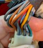
I found that my 87 stalk setup has different connectors than the old one I took off the parts car - I hadn't registered that, even though I just futzed with all that only a week ago....
I checked continuity & marked with a dot the grey that goes to the existing relay, and the blue-white.
What's nuts here is that the bl-wh in the harness is not connected to the bl-wh in the switch - that is connected with the yellow in the center pin. The bl-wh on the relay connects internally with the yellow wire, and comes back here, joins to the second bl-wh which then goes out to the wiper motor...
The switch has two grey wires. The harness side appears to have four (two per pin). The grey I marked goes to the relay. With the wipers in slow speed, the grey to relay connects to grey going to motor. I opened the harness (again) to look for the loop where it connects to the motor-feed grey, and where the bl-wh branches. I checked continuity & cut the appropriate wires to isolate the grey to the relay, and the blu-wh to the relay.
Next I have to cut the relay wires & rewire for the 99 relay. I'm also going to cut off the switch 9 pin connector & update that as well.
For the relay wiring, I'm going to:
use the two bl-wh wires to replace the grey 53m 53s positions,
use the grey for the gn-bk washer pump feed.
Yellow will be (15)
R goes to 1
add bk for ground from 31
That way I don't have to add any additional wires from the relay to the switch.
Attachments
rachaeljf
True Classic
Hi all,
Before I continue I wish to express my concern and condolences for what has been going on in the US Capitol and the tragic loss of four lives. The world is watching with dismay.
If you look at my full diagram you will see the wiper motor incorporates a changeover switch. It is operated by a cam on the gear wheel. Whenever the gearwheel is anywhere but in the park position, the switch applies a 12V ignition feed (orange wire) to the motor (via a convoluted circuit involving the grey/black wire), regardless of the wiper stalk position. This ensures the motor runs until it gets to the park position. When the gear gets to the park position, the switch flips and applies a connection to the blue/white wire. The blue/white wire is floating if the wiper stalk is in any position other than off. When the stalk is in the off position the blue/white wire is grounded. This shorts the motor windings to ground . This ensures the motor stops quickly and accurately with no risk of overrunning such that it gets into another run cycle. The relay mods I have seen generally lose this feature because the relay breaks the grey - grey/black wire circuit to the motor windings, rendering the blue/white side of the changeover switch redundant. It can be restored by using a changeover relay as I described. I think in most cases there is no problem with losing the motor brake feature as stiffness in the wiper mechanism does the job anyway.
For easier reading, the Fiat wiring diagrams tend to show wires joined in mid-loom when in reality they are joined at a crimp terminal. This is why you often see two wires coming out of some connector terminals and makes for a confusing plethora of wires!
Before I continue I wish to express my concern and condolences for what has been going on in the US Capitol and the tragic loss of four lives.
The world is watching with dismay.If you look at my full diagram you will see the wiper motor incorporates a changeover switch. It is operated by a cam on the gear wheel. Whenever the gearwheel is anywhere but in the park position, the switch applies a 12V ignition feed (orange wire) to the motor (via a convoluted circuit involving the grey/black wire), regardless of the wiper stalk position. This ensures the motor runs until it gets to the park position. When the gear gets to the park position, the switch flips and applies a connection to the blue/white wire. The blue/white wire is floating if the wiper stalk is in any position other than off. When the stalk is in the off position the blue/white wire is grounded. This shorts the motor windings to ground . This ensures the motor stops quickly and accurately with no risk of overrunning such that it gets into another run cycle. The relay mods I have seen generally lose this feature because the relay breaks the grey - grey/black wire circuit to the motor windings, rendering the blue/white side of the changeover switch redundant. It can be restored by using a changeover relay as I described. I think in most cases there is no problem with losing the motor brake feature as stiffness in the wiper mechanism does the job anyway.
For easier reading, the Fiat wiring diagrams tend to show wires joined in mid-loom when in reality they are joined at a crimp terminal. This is why you often see two wires coming out of some connector terminals and makes for a confusing plethora of wires!
Dr.Jeff
True Classic
That makes more sense, the same as other vehicles I'm familiar with. Thanks Rachael.If you look at my full diagram you will see the wiper motor incorporates a changeover switch. It is operated by a cam on the gear wheel. Whenever the gearwheel is anywhere but in the park position, the switch applies a 12V ignition feed (orange wire) to the motor (via a convoluted circuit involving the grey/black wire), regardless of the wiper stalk position. This ensures the motor runs until it gets to the park position.
No kidding. Reading @lookforjoe's last post is like an episode of Abbott and Costello's "who's on first".Damn that is a lot to parse.
lookforjoe
True Classic
Only had time to rewire the switch / harness side. Removed the y/bl-wh wires from the switch side, I'll cut them off after I've confirmed everything works as it should. I used Sumi TS090 series housing & terminals. Hopefully I'll get the relay harness routed & relay end wired tomorrow.
switch side. -male


harness side - female


Have the ground wire run to the relay panel, just need to move all this there & re-pin for the new relay (timer terminals). Continuity checked & labelled them one at a time, I'm very good at mixing things up if not attended to immediately .

switch side. -male
harness side - female
Have the ground wire run to the relay panel, just need to move all this there & re-pin for the new relay (timer terminals). Continuity checked & labelled them one at a time, I'm very good at mixing things up if not attended to immediately .
Last edited:
Dr.Jeff
True Classic
That "drop light" in your last photo brings back memories. It reminds me of the old school type of work light my dad had when I was a little kid, and I also had one for years (no idea what happened to that one). A incandescent bulb would get the metal reflector housing hot enough to burn you.  These days using a new style LED bulb in something like that greatly reduces the heat from the light.

These days using a new style LED bulb in something like that greatly reduces the heat from the light.lookforjoe
True Classic
That "drop light" in your last photo brings back memories. It reminds me of the old school type of work light my dad had when I was a little kid, and I also had one for years (no idea what happened to that one). A incandescent bulb would get the metal reflector housing hot enough to burn you.
Actually, Jeff, I want the heat - it's in the 30's in my leaky garage, even with a propane heater. The lamp provides some additional heat next to my head when I'm working under the dash.
power timer (6.3mm) termnials for the relay. These have spring sleeve around the tangs to maintain better contact.
Dash wiring mostly resolved (believe it or not)
Testing the wipers, everything works EXCEPT the delay function - I only get one sweep.
I have a bunch of Volvo relays .....
They are wired the same as the VW relay, just no variable delay. I'll have to try one tomorrow & see if at least the regular delay works.
lookforjoe
True Classic
No worries. In that case:
Cut the grey wire running from the switch to the motor (or low speed relay terminal 86 in your case). Connect the motor/relay end to 53M and the switch end to 53S. This needs to be done as the original interrupt relay and the 99 relay work slightly differently.
Hey - Rachel - I think I read this wrong - I cut the loop that joined the relay gy to the motor gy at the switch connector, and added a new wire from the relay back to the gy at the connector to feed to the motor.
The delay does not work.
What I didn't do, was to remove the two grey wires from the switch that go to the motor, so 53m is connected to the switch, and to the motor. I'm now presuming I should have left those disconnected? I can't remember if I measured any continuity between the two sets of grey wires coming from the switch after I cut the loop - so maybe there is a backfeed now...
Last edited:
rachaeljf
True Classic
Hi Hussein, the grey wire from the switch needs to go to 53S on the 99 and nowhere else. The grey from the motor (i.e. your low speed relay 86) goes to the 53M on the 99 relay and nowhere else. With the wiper stalk in the intermittent position, you should have 12V ignition on the red wire, in any other position it should be zero V. I'm pretty sure that's correct. I will need to check my wiring diagrams now! Unfortunately both my cars with 99 relays are not with me at home.
lookforjoe
True Classic
Are the low and high speeds working normally?
Yes. Only the delay doesn't work - I get one sweep - I can hear the relay click on/off on the sweep
Hi Hussein, the grey wire from the switch needs to go to 53S on the 99 and nowhere else. The grey from the motor (i.e. your low speed relay 86) goes to the 53M on the 99 relay and nowhere else. With the wiper stalk in the intermittent position, you should have 12V ignition on the red wire, in any other position it should be zero V. I'm pretty sure that's correct. I will need to check my wiring diagrams now! Unfortunately both my cars with 99 relays are not with me at home.
OK - so I need to remove the grey wire connection (for 53m) that goes to the switch then. I'll try that today - so it will look like lower right drawing (in terms of 53s & 53m connections only)
Last edited:
Dr.Jeff
True Classic
Also keep in mind there are at least two versions of the VW relay, with different delay "programming" instructions for each of them. So if you happen to have one that requires a program process other than what you did, it might not have recognized it and therefore not performing the delay function.
lookforjoe
True Classic
Also keep in mind there are at least two versions of the VW relay, with different delay "programming" instructions for each of them. So if you happen to have one that requires a program process other than what you did, it might not have recognized it and therefore not performing the delay function.
Good point. Mine (as pictured above) is the "99" 1HM 955 531 A relay - I assumed this is the delay/wait xxxsecs/off/delay to set the function, but maybe it's not.
I also need to try it again. since I may have been doing:
on/ count xxxsec / off / on again
instead of: on/ off xxxsec / on
I don't recall . Reading this VW thread whilst looking up the really # made me question how I did it - it did confirm I have the correct relay
"
Here's how you set the delay:
1) Move wiper stalk to intermittent position
2) Return to "off" position
3) Wait desired interval then push back to intermittent. Whatever time delay you set it with, it will remember that speed until you repeat steps 2 & 3."
Using a Volvo relay, everything works as it should (without programming feature). Wipers sweep 4x with wash, delay works, low & high speed work.
The two grey wires at the switch have to be connected to 53M, otherwise the wipers don't park at the end of sweep in any mode.
Installed the relay socket in the same location as the factory - just different mount & facing downward
Volvo relay in there for now, until I sort out the VW programmable one
Last edited: