Velocity Stacks on 40 DCNF's

It is a limitation of the DCNF that it can't have proper stacks. The bore spacing is too tight. IDFs can have but never seem to. They usualy have the cheapie sharp edge impression of a stack
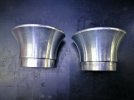
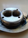
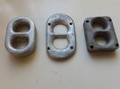
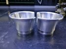
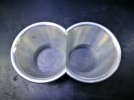
TWM make them... with a full radius rollback
40DCNF TWM ramtube.jpg

carburettors 098.jpg


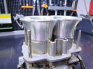
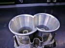
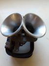
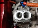
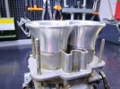
the OE style also work very well... which come in a couple of different heights, like 50 and 60 mm overall ... simply chop the tops off the stock DCNF, and they fit straight on. On a 1600 with 40DCNF's, going from 32 chokes to 34 chokes and adding bellmouths added 8 RWHP, from 101 to 109 at the wheels.

Not sure who did this, pictures from online that I found sometime...
dcnf a.jpgdcnf b.jpgdcnf c.jpgdcnf d.jpgdcnf e.jpg
a fair result that would probably be better than standard

or make your own, as shown by Brad Garska earlier in this same thread

SteveC
 
TWM make them... with a full radius rollback
Yes but no but. Each stack needs to be phyically separated from the other and they should certainly not intersect. I can't remember the rule for separation distance. You just do not get maximum flow if the flow fields interfere - robbing peter to pay paul etc. Yes I accept that the compromised solution are better than nothing but.. I think there would probably be gains with a design that leaned the individual stacks away from each other in a gentle curve. Yeah, straight is best but the effect from proper entry [full radius, no interference] would probably offset minor curvature. I will model some up.
 
Oddly, the 124s that came from the factory with IDFs had the straight blunt end stacks. One wonders what the restriction was for normal street driving range. The straight edge blunt stacks flow the worst. Also, the top of the stacks were a might close to the inside face of the factory air cleaner top.
 
Yes but no but. Each stack needs to be phyically separated from the other and they should certainly not intersect. I can't remember the rule for separation distance. You just do not get maximum flow if the flow fields interfere - robbing peter to pay paul etc. Yes I accept that the compromised solution are better than nothing but.. I think there would probably be gains with a design that leaned the individual stacks away from each other in a gentle curve. Yeah, straight is best but the effect from proper entry [full radius, no interference] would probably offset minor curvature. I will model some up.
Unless you're chasing that last 0.001hp then I wouldn't bother... how well you can get cold air to a set of OE or TWM bell-mouths will make more difference than all the effort to have totally separate bell-mouths for each throat ... the bell-mouths definitely make an appreciable / measurable difference over the stock 40DCNF configuration.

SteveC
 
TWM make them... with a full radius rollback
View attachment 79189
View attachment 79190

the OE style also work very well... which come in a couple of different heights, like 50 and 60 mm overall ... simply chop the tops off the stock DCNF, and they fit straight on. On a 1600 with 40DCNF's, going from 32 chokes to 34 chokes and adding bellmouths added 8 RWHP, from 101 to 109 at the wheels.

Not sure who did this, pictures from online that I found sometime...
View attachment 79191View attachment 79192View attachment 79193View attachment 79194View attachment 79195
a fair result that would probably be better than standard

or make your own, as shown by Brad Garska earlier in this same thread

SteveC
SteveC - I'm interested in the TWM velocity stacks but can't seem to find them on the web. Can you point me in the right direction to find them?
 
I have a collection of "velocity stacks" for the DMTR. Sadly I have no dyno time to figure out which design works best, but from what I've read, the full radius velocity stack like the TWM pictured above works the best.
Here's an example of a design that is physically separated and does not intersect on the very tight spacing of the DMTR carb.
20201007_121026.jpg
Also for the DMTR - Here are a few "fully radiused" examples that do share one side. (some are less crude!)
20201007_115140.jpg20201007_115417.jpg
Here's an example that's not fully radiused.
20201003_182859.jpg
I would love to have some flow bench time to do some evaluations!
 
Just curious - How would the velocity stack(s) pictured below be attached to the carb so they could be removed?
dcnf d.jpg
 
I have a collection of "velocity stacks" for the DMTR. Sadly I have no dyno time to figure out which design works best, but from what I've read, the full radius velocity stack like the TWM pictured above works the best.
Here's an example of a design that is physically separated and does not intersect on the very tight spacing of the DMTR carb.
View attachment 79218
Pretty damm'd close! - but no cigar. The lips must be separate or there is a dead zone.
 
A decent look at the problem "Best Bell". This looks at best cross sectional shape for a bell/trumpet wrt flow. One of the problems that gets a mention is corners [anything not truly circular has corners] and sharp edges.
 

Attachments

  • RET_Bellmouth_Sept.pdf
    1.7 MB · Views: 52
Thanks, you're right - not cheap! I wonder how these might be "printed"?
I've printed a few for IDFs. One of them was a shorty bellmouth so there would be plenty room overhead in the usual rectangular filters. I used a metal velocity stack to dimension the base, made it thicker since plastic vs metal, then added any shape I wanted on top of that.

I've been planning to make some for DCNFs, DMTRs, and DCOEs but haven't gotten around to it yet. The angled stacks referenced in this thread makes me want to get on with it.

So, yeah. I like your idea.
 
At 50mm tall, squeezing the OE type bell-mouths into an airbox that fits in the bodywork confines is a challenge...

You know to test anything you'll need to buy a pair of OE bellmouths anyway, to be able to back to back test them on a dyno. While a computer simulation may show a minor improvement, nothing beats real world testing... simply putting a curve in the inlet may focus the highest air flow off to one side of the carb, so not aimed in the middle where the aux venturi discharge is.... a carby afterall has two functions, to control the amount of air the engine can inhale, and mix a pre determined amount of fuel with that air... and at the same time atomise that fuel down to a functional and the most effective droplet size.

Not knocking the idea, but there would be a greater % increase in flow available from some "blue-printing" of the actual carb insides... the venturis often have a decent casting ridge, the butterfly screws protrude from the throttle shaft, and the stock tall 40dcnf aux venturi can be shaped for much better flow, all these are much bigger impediments to air flow than a sectioned / truncated bell-mouth.

SteveC
 
but there would be a greater % increase in flow available from some "blue-printing" of the actual carb insides... the venturis often have a decent casting ridge, the butterfly screws protrude from the throttle shaft, and the stock tall 40dcnf aux venturi can be shaped for much better flow, all these are much bigger impediments to air flow than a sectioned / truncated bell-mouth.
I don't see this as either or but rather lets do all the above. This sort of work is very good bang for buck
 
nto an airbox that fits in the bodywork confines
from a personal perspective, I expect to be doing a new engine cover anyway. Weight reduction, more ventilation and more space. Anything other than the stock aircleaner is just too tight [in my opinion]
 
I don't see this as either or but rather lets do all the above. This sort of work is very good bang for buck
It is if the engine is under carbed... which in the case of the 1600 it obviously is with 40DCNF's which was a design choice to benefit street drive-ability and chasing torque rather than gross Hp numbers. - hence the big jump in power and torque from a larger choke (32 to 34) and fitting the bellmouths, with absolutely no other changes, i.e. no ignition or cam timing changes, so yes they were very good bang for buck... but the rest of the engine was there to support it and required the extra flow.

If the engine was sufficiently or over carbed - say a 1300 that was built for street and revs to 7500/8000 max and makes under 100hp at the wheels - then improving the carb / inlet efficiency with the addition of bell-mouths of blue-printing internals to increase airflow, won't have as marked results. If you have a 1300 that revs to 9000plus and makes in excess of 100hp at the wheels, then absolutely... to get there it can't be an either /or build... you need to cross all your t's and also dot your i's and j's.

I asked Mark about printing up some carby / manifold spacers on his 3D printer - he's a techno-phile who works in the IT industry and has all the nice gadgets - and he reckons commonly available printing materials don't like the heat...maybe above the carb is different? I know the Ducati twin's that use a single 44DCNF have a plastic spacer above the carb and then a plastic bellmouth inside their plastic airbox, but I'd guess that's injection moulded ABS type material

SteveC
 
commonly available printing materials don't like the heat...maybe above the carb is different?
How hot is the question. There are plenty of common filaments being used in engine bays for all sorts of things including trumpets. ASA [about AUD40/kg] is being used for this and it is good for 100 degrees C at low mechanical load = trumpets. There are plenty of glass and carbon fibre filled nylons [about AUD200 and up /kg] available. They are much stronger/stiffer and good for 150+ degrees C. I would be nervous about a plastic manifold on our engines as non-crossflow and detail design means the exhaust manifold is virtually touching the inlet manifold. I am also yet to be convinced on long term use.

I am focused on printed parts as patterns rather than serviceable items themselves. I will investment cast in ally for something like a manifold. I would prototype trumpets in ASA and be tempted by carbon/nylon for servicable parts.
 
Last edited:
carby / manifold spacers
I think the glass or carbon filled nylons would be ok for this. I would be worried about creep on any plastic less dense that a phenolic. I guess it depends on how long you want the part to last and or how often you want to tighten the bolts :)
 
Back
Top