x1/9 headlight Mod. Help!!

Keithx1/9

Daily Driver
Ok. So I did the brown wire Mid and I am I. The middle of the Headlight Mod

I believe that I am following the instructions posted pretty well(thank you for the post) I am at the point where it says to unwrap the wire harness to tap into the high and low beams. Where do I go for this? Inside the car? Run more wires to my new fuse box in the front trunk? I am sordid this question sounds dumb but I am confused now.
Please help ?Thank you all in advance
 
I am not sure which instructions you are following, but I dislike "tapping into" factory wires as much as I dislike cutting them. I would get a pair of male H4 plugs like these (I know nothing about those in particular, but find that type in a quality you like). You plug these into the factory headlight sockets in the pods, and get ground, high beam and low beam signals for you relay set. You could use one only, and control both relay sets from either the left or right pod. Or you could use one for each side and control the left relay set from the left pod socket and the right side relay set from the right side pod socket.
 
I am not sure which instructions you are following, but I dislike "tapping into" factory wires as much as I dislike cutting them. I would get a pair of male H4 plugs like these (I know nothing about those in particular, but find that type in a quality you like). You plug these into the factory headlight sockets in the pods, and get ground, high beam and low beam signals for you relay set. You could use one only, and control both relay sets from either the left or right pod. Or you could use one for each side and control the left relay set from the left pod socket and the right side relay set from the right side pod socket.
Thank you for your input

so please walk me though. Tjis is where I am at. i mounted the two relays. What do I do from here? I can buy those items that you suggested
Thank you so much

1. Mount the 30A relays to the firewall next to the new fuse block. Be sure the relays are well GROUNDED by scraping away paint. They need the body as a ground source in order to operate... much like your horns.

2. Carefully unwrap the wiring harness to expose all the wiring. Look for 4 wires that are black with grey stripes, and black with green stripes. Separate them out of the loom so that they can be cut and lengthened... in order to operate the relays. DO NOT CUT THEM YET!

3. Cut EIGHT pieces of tape and use a marker to mark the wires, 2 each, LH, LL, RH, RL... for Left High, Left Low, etc.

4. Turn on the headlights and switch from high to low and insure all four lights are working... Left Low, Right Low, Left High, Right High. With the lights still on... CUT one wire. Note which light went out... if none initially, then switch the high beams on... Mark the cut ends of the wire with the appropiate tape label. Do this with all four wires and all 8 pieces of tape.

5. The relays should have their leads marked with L, S, and B. L is for LOAD, in this case the lights, B is for battery, or the new voltage source, and S is for switch, or the "trigger" source. If they are different, you will need to determine what each function is for the relay you have.

6. Run one wire from Fuse 2 to the B post of one relay... run another wire from Fuse 3 to the B post of the other relay. (Now each relay has a fused source of power directly from the battery... DO NOT install the fuse yet.)

7. Locate the two wires marked RL and LL coming from the cockpit... and twist them together. Add a length of wire from these two to the S post of one of the relays. LABEL this relay LOW. Locate the other two wires marked RH and LH from the cockpit, twist them together and add a length of wire and tie thes to the other relay's post marked S. Label this relay HIGH.

If you turn on the lights now... the LOW relay will click as you turn on the switch... and the HIGH relay will click when you activate the high beams. (no lights will light yet though.)

This is a good test to this point though...

8. Lastly, locate the two LL and RL wires going to the lights, twist these together and add a length of wire and tie it to the L terminal on the LOW relay. Do the same with the RH and LH lead and tie to the L of the HIGH relay.

9. Insert fuses and test.

10. Happiness abounds and LOADS of light. While yur at it... make sure all grounds are good coming off the lights in the pods...

11. You have one or two fuses left... I suggest you buy a 15 - 20 dollar air horn set from Harbor Freight or Pep Boys and use this as a source of power for them. Horns will mount inside the LEFT LIGHT POD and I guarantee... you will never go unnoticed again!
 
Keith,

That is a very old set of instructions. Currently the path to succeed is buying an insertable kit. I used a cheap kit from Amazon that cost around $20. It is the same idea as the instructions you are following, but leaves the stock wiring intact.
 
Regardless of what path you choose, the basic idea is to use the existing headlight circuits only as a trigger signal into the low side of the added relays. Your newly added fuses/relays/heavy gauge wires will then supply the power to the headlights. Perhaps take a look at some relay diagrams online to see how they transition a low current signal (the old headlight harness) to a high current power supply (your newly made harness). That may help to better understand what goes where. ;)
 
Keith,

That is a very old set of instructions. Currently the path to succeed is buying an insertable kit. I used a cheap kit from Amazon that cost around $20. It is the same idea as the instructions you are following, but leaves the stock wiring intact.
I installed one of the amazon kits on one of my cars. Easy install very happy, I could not buy the parts for the cost of the kit. and the kit looked to be of decent quality
 
Thank you for your input

so please walk me though. Tjis is where I am at. i mounted the two relays. What do I do from here? I can buy those items that you suggested
Thank you so much

On your car I would not do it that way. The brown wire was a kludge which makes more amperage available to put through the same contacts in the ignition switch, this frankly does not solve the base problem of power getting through those now old and likely carboned up contacts to supply everything.

I am not a fan of the kits which put non weatherproof relays in the front headlight area, perhaps I am just an alarmist :) but I lived in a wet and often salty climate growing up and know electronics and salty water don’t mix in a positive way.

I would do the following:

First you have an ‘85 which uses the new wiring system.

This system already has a relay for the high beams. This is a completely adequate relay and the wiring has no joints in it running from the fuse/relay box to each light so the losses are minimal. My car has H4s with 60w bulbs and has no issues with this and my output is about the best it could be (yes it could be marginally better if I put a 10ga power supply to a relay right next to the bulb which is what the Bob Brown solution does).

Your car has AC (please add details about your car to your signature (85 FI w/AC) as it makes it easier and faster for others to assist you) which means you will have to do a little more work.

If your car did not have AC you would have a block of unused relay bases and wiring already next to the fuse box, however you have AC so you will want to add a relay to directly power the existing two fuses which protect the wiring to the low beams.

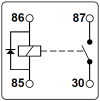
Buy a relay which is a normally open 4 pin but with a diode and a single 87 output post. Get a relay base for the relay type you have chosen, buy a good quality relay preferably with a diode, this is an example of the relay you want: https://www.amazon.com/Bosch-Automo...ocphy=9051962&hvtargid=pla-575461746378&psc=1

6471C790-EF61-4620-B380-21909E5BAD72.png

Buy good quality crimp connectors with locks which work with the relay block and sized relative to the wires you want to use.
This is a good source among many:


You will be looking for something like this for the 10ga wires and a similar version for the 12-16ga wires
6.3mm - .250 Tin Plated Brass Locks into Housing
Female Terminal by AMP
2 - 4 mm2 (10 - 12 AWG)
Fastin/Faston - Locks into Housing
AMP 1012 Locking

Do not use the crap that comes with cheap relay blocks or is generally available at a mass market auto parts store.

Undo your fuse block assembly and look at the back of it. You will see a nice variety of wires going to the box in blocks of wires, note the letters next to each block. Within each block the wires run from top to bottom numbered to relate to the wiring diagram which I have attached to this post.

36FAB29A-52DB-49F7-94EB-73F51E6E861B.jpeg

You will be removing one wire which is coming from the hi/lo switch, it is gray with a red tracer and heavy gauge, it lives in the D connector, position 2 (they are numbered). You can see it in this picture I took from my spare fuse box. This particular wire feeds power from the ignition switch to the light switch to the hi/lo beam switch to then provide that power to the two fuses which feed the low beams. What you are about to do will reduce all of those connections to just the fuse/relay box.

DED7BCD5-C974-4A56-B153-E5A08A5B2DB3.jpeg


The wire you removed will be going to your new relay as the relay exciter on pin 85. On the relay you will run a wire to ground from the 86 pin using 18ga wire. You will need to bring power to your 30 pin from the battery with a 25A fuse and a new wire to go to position D:2 of the fuse box connector. The last two wires feeding power from the battery to the relay and the relay to D:2 will be 10ga wire.

This is a nice modification which could be put back to standard if needed with almost no effort, just moving the wire from the relay back to D:2

In regards to the brown wire I will go over that in another post. This is a bit involved (or at least I am making it that way :) I am waiting on a couple of parts for my build of this so I can’t show you a pic.
 

Attachments

  • X19 BERTONE Wiring.pdf
    527.7 KB · Views: 85
Last edited:
Fitting a starter relay should be on your list as well, this requires a minor amount of destructive modification to two wires and adding a relay and one 10ga wire which are easily done in the spare tire well. If you are interested I can delineate this modification for you as well.
 
Fitting a starter relay should be on your list as well, this requires a minor amount of destructive modification to two wires and adding a relay and one 10ga wire which are easily done in the spare tire well. If you are interested I can delineate this modification for you as well.
Yes I would like to do this one as well. How do I do it? Thank you so much
 
The starter relay is more involved in regards to what you need to do and requires unwrapping the loom in the spare tire well to pull out an existing wire which you will use in two ways. You will be adding a wire to carry power from the main lug of the starter to the new relay and of course adding a grounding wire.

You will need:
  • One inline crimp splice connector with heat shrink - 12-10 AWG Clear Seal Heat-Shrink Butt Splice Terminal (not a big fan of these but its what you need)
  • One 10mm ring crimp connector for 10ga wire
  • One 8mm ring crimp connector for 12-16ga wire
  • Two locking female spade connectors for 10ga wire to go into a relay base
  • Two locking female spade connectors for 16ga wire to to into a relay base
  • One relay base
  • One relay, normally open 4 pin 35amp with diode. This is the same relay you used for the low beams.
  • 3’ of 12 or 16ga wire, I use black for ground and red for power
  • 3’-4’ of 10ga wire, I used red
  • Nice to have is a fuse holder for a 30 amp fuse which accommodates 10ga wire. The existing circuits are not fused, if you feel confident about your work then don’t use a fuse in the power supply wire or choose a relay which has a fuse holder built into it. Like these (but buy a name brand):https://www.amazon.com/Nilight-50023R-Automotive-Wires-Auto-Switches/dp/B07PK7F1MC/ref=sr_1_4?crid=27FD6HTCRQL2P&keywords=Fused+relay&qid=1658089056&s=automotive&sprefix=fused+relay,automotive,122&sr=1-4
Remove both wires from the car battery.

The starter has four wires to it. The main lug of the starter has two wires, a very heavy red one which brings power from the battery, a medium thick black one which carries power from the alternator to the starter (and is how the power is carried back to the battery from the alternator.)

On the starter solenoid there are two wires, one red and one red with a black leader which are crimped onto a single female spade terminal which goes to the starter solenoid male spade terminal. The all red wire is 10ga and comes from the ignition switch, carrying power to the solenoid to engage the starter when you turn the key to the start position. The second wire is 12ga red with a black stripe, this carries power back to the double relay to cause the double relay to run the fuel pump when the starter is running.

Unplug the paired red wires from the starter solenoid, do not do anything to this connector you will be using this exactly as is. Loosen and remove the nut on the starter main lug holding the large red wire and the black wire.

What you will be doing is making a new 10ga wire which will have a ring terminal on one end to be added to the wires on the main starter lug and a female locking spade on the other end to go into the relay holder. This will bring always hot power to the starter relay. You will make a 8” long 12-16ga wire with a locking female terminal on one end and a ring crimp connector on the other end to be the ground for the relay.

Ok now for the fun part.

This is easiest if you remove your passenger seat and the cover for the spare tire area. To remove the seat, take a 6mm allen key (I think its 6) and slide the seat all the way back. Under the front of the seat you will see the seat slides, there is a allen socket head fastener there. Loosen the fasteners (one at the front of each track) a number of turns so the seat can be lifted just a bit, you don’t have to take the fasteners out but if you want to do a bunch of tedious work with your Allen key go for it, I am lazy). Now slide the seat all the way forward, you will see two Philips screw heads, undo these completely. As they go all the way through the floor pan of the car you might go under head the spray some lubricant on them to make them come out easier. You might also consider a hammer drill if they are at all recalcitrant. Once the two screws are removed you can slide the seat forward about half an inch and lift up on the front of the seat and the allen bolts will come through the keyhole slots and you can remove the seat completely.

Remove the spare tire cover by removing the philips screws holding the black metal bracket holding the vinyl cover in place. Remove the spare tire. Remove the clamp connector holding the 5/8” heater supply hose to give yourself some more room.

Along the tunnel you will see a thick wire bundle wrapped in tape. There are a few bent over metal retainers in the spare tire area you will bend out of the way. Up above you will see the double relay which has the its own wiring, you won’t be touching that, there is also a second relay which runs the FI injector cooling fan, again you won’t be touching that unless you want to (I moved mine up higher so I could use the threaded stud to mount my new relay).

Take an 18” length of red 12-16ga wire and crimp a locking female spade connector at one end to go into the relay holder. The other end your will be eventually crimping the inline connector to it and the red 10ga wire coming from the ignition switch.

Pull the wire bundle out and carefully slit the electrical tape covering, starting at the floor and going up to just above the top of the tunnel. Buried in the bundle is a 10ga red wire, this is the wire running from the ignition switch to the starter solenoid. Pull it out of the bundle so you can access the 10ga wire near the floor. If you are not confident you have the right wire you can test for continuity by testing between the 10ga wire you have found and the red with black leader wire going into the double relay, as these wires are connected at the female spade connector they will have continuity when tested. If you have a steel pin you can pierce the insulation touch your meter to and then poke the other probe into the bottom of the double relay connector where the red with black leader wire goes into it to ensure the wires are connected at the female spade connector at the starter.

D54341CE-F8E8-48D6-BC95-E9D3E17A9686.jpeg


You will be cutting this wire to bring a wire to the relay to switch the relay “on“. You will cut the wire, apply an inline connector, crimp it to the 10 ga wire on one side, then crimp in an 24-36” length of 12-16ga wire and apply heat to seal the crimped connector to the wires (10ga on one side of the connector and 12-16ga on the other). I say this so that you consider the cut carefully as you will be down in the corner and access won’t be good. You are trying to maximize the amount of the 10ga wire you will be using to go from the new relay to carry power to the starter solenoid and still be able to work with what is sticking out of the harness at the floor. I cut mine such that I had 1.5” of the wire sticking out of the harness to crimp the 12-16ga wire to the 10ga wire coming from the ignition switch.

FYI, have a fire extinguisher handy when you use heat or flame on the crimp connector, the sound insulation is very flammable. It is bad form to burn your car down while heating heat shrink tubing…

OK so now you have a length of 10ga red wire coming from the firewall side and the 12-16ga red wire you just crimped onto the wire coming from the ignition switch. Pull the 10ga up out of the bundle to where it goes into the bundle where it goes through the firewall into the engine bay.

Weave the 12-16ga wire into the wire bundle such that it will thenemerge where the 10ga wire goes into the engine bay and wrap the bundle in electrical tape leaving the 10ga wire and the 12-16ga wire coming out at the top of the tunnel to be able to go to your new relay. For my new relay I used the threaded stud the FI fan relay was attached to and moved that one up with a new fastener (I used a short sheet metal screw, the gas tank is behind that wall so it was a notably short screw).

Now crimp on the locking female spade to the 10ga wire and insert it into the relay holder in the 87 position (you should have enough slack in the wire to place the relay on the existing threaded stud for the fan relay). Insert the red 12-16ga wire with connector into the 85 position. The wire with the other ring connector will go on the threaded stud (use a toothed washer to ensure good ground) and the locking female connector into the 86 position of the relay holder.

1B755287-3031-4E8B-93EB-1C7900A99CD0.jpeg


For the power wire I crimped on the 10mm ring connector to the 10ga wire. Pushed the 10ga wire with the ring connector on it through the black flap where the acclerator cable goes into the engine bay. I then put together the new wire with the existing large red wire and the black wire onto the main lug of the starter. Make sure you feed the new 10ga wire into the rubber boot so it is protected along with the other wires. Fix the new red wire to other wires leading up to the flap into the spare tire area such that it doesn’t foul on anything but has enough slack for engine movement and for when/if you have to replace your starter. I left an extra loop in the spare tire compartment so it can be pulled a bit into the engine bay if needed. The new red wire will go into the relay’s 30 position.

Back in the spare tire compartment I trimmed the new 10ga power wire to easily reach the relay position, crimped on the female spade and inserted it into the relay holder 30 position

Install the relay, attach the battery, put the spare tire cover back on, put the spare back in and reinstall the passenger seat.
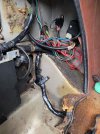
D98CFF54-5346-4CB8-AE7D-B0B10310B1F0.jpeg

For those looking carefully at my pic you will notice I did mine on this car slightly differently. The PO, who I dislike mightily, had used a wire tap to reinstall the red wire with black leader to the main red wire at the solenoid spade connection. This had caused intermittent starting issues in the past so on my install I cut the red with black leader wire in the spare tire compartment and crimped it onto the red wire at the relay 87 position. The exact way this is done will change a bit in the future as I used some parts I had on hand to do this and it is less than ideal (cheap relay holder with cheapo connectors, all the things I say not to do…) as I only found the PO’s handiwork when replacing the coolant hoses. The wires will get some future tidying so its a bit less of a rats nest.
 
Last edited:
On your car I would not do it that way. The brown wire was a kludge which makes more amperage available to put through the same contacts in the ignition switch, this frankly does not solve the base problem of power getting through those now old and likely carboned up contacts to supply everything.

First you have an ‘85 which uses the new wiring system.

This system already has a relay for the high beams. This is a completely adequate relay and the wiring has no joints in it running from the fuse/relay box to each light so the losses are minimal. My car has H4s with 60w bulbs and has no issues with this and my output is about the best it could be (yes it could be marginally better if I put a 10ga power supply to a relay right next to the bulb which is what the Bob Brown solution does).

Your car has AC (please add details about your car to your signature (85 FI w/AC) as it makes it easier and faster for others to assist you).

If your car did not have AC you would have a block of unused relay bases and wiring already next to the fuse box, however you have AC so you will want to add a relay to directly power the existing two fuses which protect the wiring to the low beams.

Buy a relay which is a normally open 4 pin but with a diode and a single 87 output post. Get a relay base for the relay type you have chosen, buy a good quality relay preferably with a diode, this is an example of the relay you want: https://www.amazon.com/Bosch-Automo...ocphy=9051962&hvtargid=pla-575461746378&psc=1

View attachment 63868

Buy good quality crimp connectors with locks which work with the relay block and sized relative to the wires you want to use.
This is a good source among many:


You will be looking for something like this for the 10ga wires:
6.3mm - .250 Tin Plated Brass Locks into Housing
Female Terminal by AMP
2 - 4 mm2 (10 - 12 AWG)
Fastin/Faston - Locks into Housing
$0.25 each AMP 1012 Locking

Do not use the crap that comes with cheap relay blocks or is generally available at a mass market auto parts store.

Undo your fuse block assembly and look at the back of it. You will see a nice variety of wires going to the box in blocks of wires, note the letters next to each block. Within each block the wires run from top to bottom numbered to relate to the wiring diagram which I have attached to this post.

View attachment 63866
You will be removing one wire which is coming from the hi/lo switch, it is gray with a red tracer and heavy gauge, it lives in the D connector, position 2 (they are numbered). You can see it in this picture I took from my spare fuse box. This particular wire feeds power from the ignition switch to the light switch to the hi/lo beam switch to then provide that power to the two fuses which feed the low beams. What you are about to do will reduce all of those connections to just the fuse/relay box.

View attachment 63869

The wire you removed will be going to your new relay as the relay exciter on pin 85. On the relay you will run a wire to ground from the 86 pin using 18ga wire. You will need to bring power to your 30 pin from the battery with a 25A fuse and a new wire to go to position D:2 of the fuse box connector. The last two wires feeding power from the battery to the relay and the relay to D:2 will be 10ga wire.

This is a nice modification which could be put back to standard if needed with almost no effort, just moving the wire from the relay back to D:2

In regards to the brown wire I will go over that in another post. This is a bit involved (or at least I am making it that way :) I am waiting on a couple of parts for my build of this so I can’t show you a pic.
Thank you
It is an AC Car. Where should I put this information for further help? Thank you
 
Thank you
It is an AC Car. Where should I put this information for further help? Thank you
Go up to the top of the page, click on your name, choose ’Signature’ put in there what want.

Sorry it wasn’t meant as an admonishment. It just makes it easier to quickly parse what advice you need. Fuel injection vs carb, early vs late and any major mods like 1600, shaved head, high compression pistons etc

I put in the general information about my cars in simple short hand. FI stands for fuel injection, AC or no AC. If your car was notably modified you might add some other info about your modifications. I also added my location. Sometimes it is useful for someone to know roughly where you are so if someone is nearby they could reach out to offer assistance. Clearly this is entirely up to you and what you are comfortable with.

Happily there are not a huge variety of differences among them until we start modifying them :)
 
Keith,

That is a very old set of instructions. Currently the path to succeed is buying an insertable kit. I used a cheap kit from Amazon that cost around $20. It is the same idea as the instructions you are following, but leaves the stock wiring intact
 
Hi Jim

thank you I just received my kit from Amazon. Anything special I should I do or look out for as I attempt to install it? Thank you again Keith
 
Hi Jim

thank you I just received my kit from Amazon. Anything special I should I do or look out for as I attempt to install it? Thank you again Keith
The biggest thing is making sure the power supply wires are long enough and are actually 10ga. Be prepared to replace them and the connectors associated at either end.
 
Hi Jim

thank you I just received my kit from Amazon. Anything special I should I do or look out for as I attempt to install it? Thank you again Keith
Read through the post I linked earlier. My experience is logged there and others added comments.
 
Back
Top