Jepp78bertone
True Classic
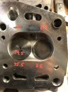
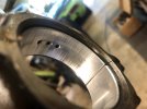
Here is the template I made to open up the combustion chamber shape. Template is a direct trace of the stock 1500 combustion shape


Change of Plans and Finally executing some progress.
It has been 2 years since I've made any progress on the x19 engine build and its about TIME to get it back on the road.
However I've made some changes to the engine build plan and I'd like to share this process as I put it all together.
The old plan was to use the original US spec 1500cc cylinder head milled down to remove the circular recess to bump up compression. The machine shop ended up removing 0.085" stating that they needed too to ensure the head surface was perfectly flat, even though I had requested they only milled enough off to remove the circular recess. I measured the combustion chambers with my burette and they only measured between 25.2-26cc resulting in my CR being far higher than I had anticipated and it was simply a poor choice on my end to have the head milled without specifically clarifying that the max amount removed should be no more than 0.065"-0.070".
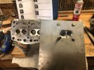
So I've abandoned that head and am starting fresh with a brand new NOS Yugo 1100cc head that I will modify in similar fashion to the way Rob Plenter did his on his 1603cc engine build. See his thread for his awesome build including what he sourced for a lightweight valvetrain. Which I wish I could afford doing myself. https://xwebforums.com/forum/index.php?threads/1603cc-engine-build.25589/
CYLINDER HEAD build plans are as follows
- starting with a NOS yugo 1100 10 bolt head w/ 36/31mm IN/EX valves
- M10 stud holes will be drilled out to M12 to fit ARP head studs
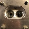
- Combustion chambers opened up from 80mm to 86mm to suit 1500cc bore size. Initially just copying the stock 1500 combustion chamber shape until later to fine tune the cc and maximize swirl into the cylinder - Essentially trying to replicate a 1500 EURO head
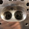
- All seats are being replaced to suit 39.5mm Intake and 33.4mm exhaust valves
- Ports are being opened up to 28.5/29mm and Bowl work blended into larger seats as per stevec's ultimate SOHC guide
- Bronze valve guides to be installed and trimmed back to be flush with port roof
- 3 angle valve job and 30degree back cut on all valves
- sinking the exhaust valves slightly lower than the intake valves as per stevec's recommendation (plus i'll be using my old 33.4mm exhaust valves from my old head and they have been ground a touch before so this will move them up a tad to match the brand new AE Intake valve length )
- cam housing surface of head shaved 1mm (0.040") to accommodate reground cam's smaller base circle
CAMSHAFT
- PIPER cams FIAX19BP300 regrind camshaft
- advertised 290 degree duration BUT I emailed Piper cams and they stated duration @ .050" = 258 degrees
- advertised Valve lift = 11.18mm BUT measured Cam lobe lift (32.9mm overall lobe height - 22.8mm base circle) = 10.1mm lift (I've emailed Piper cams to ask why this would be and if it seems right)
- Valve timing - 39-71/71-39
- Stock cam tappet buckets with 3.5mm shims (+/- 0.05mm)
- Using Alfa 8mm Lash caps to achieve Valve clearances of Intake .010" and exhaust .012"
- Still deciding on what valve springs to use - either ISKY race springs or a set of new Alquati springs. Depending what I end up confirming about the cams max lift will determine the route I take for springs.
- Adjustable Cam pulley - what I believe is a Millers Mule brand
BOTTOM END
- Stock 1500cc block bored out to fit 86.8mm pistons
- Stock 63.9mm crank and con rods / new bearings installed throughout bottom end when built in 2015
- FIAT OEM 1300 Small flycut pistons (only markings on the crown are a small stamp that says "fiat113" and the marking 6/10) CH unknown. 0.6mm pop-up "pimple"
-piston is currently sitting 0.5mm below deck at TDC, I am considering disassembling the bottom end and having the block decked to have pistons at zero deck , but still need to finalize head gasket choice/and crunch the numbers to achieve Squish/Quench of 1mm.
- Will also need to determine how to go about enlarging INTAKE fly cuts on pistons to accommodate new 39.5mm intake valves (ive heard this can be done with the pistons remaining the block, but I have yet to find any information on it, can anybody walk me through this?)
CARBURATION
-2x weber DCNF40's
-Port matched intake manifold
-32mm chokes
-ITG duel DCNF foam air filter
IGNITION
- YUGO Bosch Electronic Ignition
- Bosch Distributor
- Doug's (rx1900) premium ignition wire set
I will attach photos of progress as I go
Hi Greg,Jepp, I have almost exactly the same engine spec in my track x1/9. I have that piper cam but billet one, I find it has good torque for both on the road and track, and it still likes to rev to over 7,500rpm. I run 40 DCOEs with 34mm chokes, same valves, 4 - 2 - 1 headers, 10.7 : 1 C/R, getting about 135 hp at 7,000rpm.

The misunderstanding you had with the machine shop was likely because the top of the decompression recess is domed; I got one of Matt's performance heads for my '86 (10mm bolts) that came with a spec sheet showing a .065 shave, and the recesses weren't totally gone, there's a little left in the center.US spec 1500cc cylinder head milled down to remove the circular recess to bump up compression. The machine shop ended up removing 0.085" stating that they needed too to ensure the head surface was perfectly flat, even though I had requested they only milled enough off to remove the circular recess. I measured the combustion chambers with my burette and they only measured between 25.2-26cc resulting in my CR being far higher than I had anticipated and it was simply a poor choice on my end to have the head milled without specifically clarifying that the max amount removed should be no more than 0.065"-0.070".

you're absolutely right Jeff, It was my mistake for not clarifying the amount. Oh well, lesson learned.The misunderstanding you had with the machine shop was likely because the top of the decompression recess is domed; I got one of Matt's performance heads for my '86 (10mm bolts) that came with a spec sheet showing a .065 shave, and the recesses weren't totally gone, there's a little left in the center.View attachment 46290
just a couple of thoughts....
M12 ARP head studs will require that you machine the head bolt washer pads at the spark plug side of the engine, the ARP's are too short for this application by a few threads, so the best engineering solution is to machine the pads. Do this at the diameter of the ARP washers, not the standard Fiat washers or you will break into water on the two ends.
the ends need 11mm removed and the middle three need 6mm removed.
The PiperBP300 reground cam I have turns out to be more of a mystery than I had thought. My measurements of cam lift ended up indicating that this reground cam has an actual lift of 10.1mm, not the advertised 11.18mm. I've emailed Piper and they confirmed that on some cams sent in for re-profiling they cant get the full profile cut but that the measurements that I provided are what they would use. I have to figure out now if I'm going to stick with this cam, and figure out all of its measurements, or find something different.If you have a reground cam (poor choice IMO you should have gone for the billet) then the reduced base circle ill let you move the exhaust valve up. Obviously you loose spring tension and need to refit an extra washer or two under the spring to make up installed height and keep tension.
Plus (like most peopel) you've gone for the biggest lift / longest duration cam avaiable (another not so informed choice IMO) as you simply havent considered the DYNAMIC compression you will acheive with this combination... cam choice should be based on this.
Just go with standard replacement Fiat springs, the iskys are a compromise. and there are much better choices if you look but just not offered by the usual suspects (the usual vendors)
I have pulled the bottom end apart, and I will be replacing the rings and most likely the rod and main bearings. See new post for bottom end condition.Are you pulling the pistons to at least replace rings? 100k km is reasonable mileage and replacing the rings should give it a new lease of life.
as far as finished combustion chamber shape goes, look at well finished Chevrolet small block heads, thats the combustion chamber shape yu want to aim for.
View attachment 46224
SteveC


My pistons are now with my machinist who will be enlarging the inlet flycuts. He did contact me to ask me if I knew the exact radius size of the stock flycuts so he could find the center line and know exactly where to position the new cut?a few more thoughts,
1) I use a 22mm radius for the inlet flycut enlargement, just make sure the cut has a reasonable raduis to the inside if the cut, not a sharp / squared edge, (but your machinist should know that) and make sure you "break the edge" and smooth / round off the top sides of the cut as well, you don't want sharp / pointy edges anywhere.
I went ahead and had the block skimmed to get the piston crown level with the deck surface.2) If you are gong to retain a 300degree duration camshaft, then you really need to give thought to also skimming the block, to get the piston crown level with the deck surface, at the moment I think you said it's about 0.5mm down from zero when the piston is at TDC. You really need to get the static compression up, as otherwise your DYNAMIC compression will be too low.
I had the engine builder measure and check the crank and rods and they checked out perfectly. He says I can use STD sized bearings. He polished the crank.3) Looking at the big end bearings I would be double checking the con rod big end journal I.D. for size, perhaps they are a little out of round?
Just received my new bearings from MWB. Matt had Clevite Rod bearings in stock, and Factory OE main bearings.4) I would also try and choose a better quality big end bearing. See how the machining cuts to the bearing go "across" the grain ... at 90 to rotation ... thats the simpler method of manufacture... but the machining pattern will tend to release the trapped oil wedge, letting it flow away from where it's required. Better quality big end bearing shells will have the material machined to size by planing the material "with the grain" and the machining grooves will be along the bearing and not across it... Old Italian made Clevite and Vandervell are like this ..the grooves running this way will tend to hold the oil wedge in place a bit better.


Trying to get and keep aluminum clean is a losing proposition. Grime gets into the pores and does not want to get out or stay out, and then there's the corrosion, that white powdery stuff.You're doing nice workHow'd you get everything so clean? I am doing a rebuild right now and you've got me thinking I should out more effort into making the head and cam boxes shine.