1500cc hot street motor build

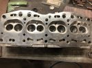
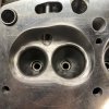
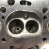
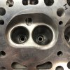
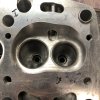
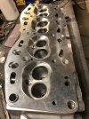
One of course being achieving 31cc in the combustion chambers.
Right now I'm at 29.5cc
Possibly use a thicker head gasket to get your target chamber volume? I love multilayer steel head gaskets, and they easily allow the thickness to be dialed in as desired.
 
Possibly use a thicker head gasket to get your target chamber volume? I love multilayer steel head gaskets, and they easily allow the thickness to be dialed in as desired.
An option indeed, but i'm hoping to keep the SQ clearance at 1-1.2mm.

I've got a few different head gaskets on hand with different thickness' to play with. But my goal will still be to maintain desired SQ by manipulating the volume of the combustion chamber.

I'll have a clearer idea of what cc's i'm working with once i have an idea of what material I can remove from the valve faces.
 
DCC33C5E-A834-4B6B-A939-F04341008284.jpeg8472DCCF-9C92-4D61-8ACA-6B353B328CFD.jpeg091E1B83-56A3-498E-B32C-458D18C1279B.jpeg373A10BF-D1A5-48B6-BAA3-1F3C2D4D12EA.jpegADD4F8E8-7DFA-4A87-B37C-18F1D9F371A1.jpegD60A93FD-31D7-43E5-90BA-7230FF8E8641.jpeg
 
looking good for a first time attempt, but a couple of points for you to ponder...

Deshrouding the inlet valve in the area marked in red, you could definitely use more material removal from around this area... you have the chamber wall angling down from the fire ring edge to the edge of the valve, it definitely needs more clearance to assist low lift flow. put a valve in place and lift it 5 - 10mm in mm increments and see how little space there is around the valves periphery in this area.
091E1B83-56A3-498E-B32C-458D18C1279B.jpeg

about 80% of the flow comes out of the area marked in blue in the picture above, deshrouding the region towards the quench pad has no benefit, and can infact be detrimental to overall flow.

the second point is bowl depth and the port roof height, you need to give it a larger bowl volume and raise the port roof more... like most forst time porters you made the usual mistake of starting at the outer face to the manifold.... and I warn about this in my chapoter on cylinder head development... you really need to begin in the area around the valve guide as this sets the roof height / bowl depth (the area I mean is roughly the region in blue in the picture below)
67063474065__11F8C912-67D4-4578-9753-209DC496D3CB.jpeg


look at these port mould pictures, see how the bowl sides are very vertical, not tapering in towards the guide boss... this and the port height really define a well developed port on these motors
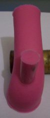
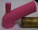
portpics 019.jpgportpics 020.jpgportpics 021.jpgportpics 022.jpg

you made yourself a lot of work starting with an 1100 head, combustion chambers can take up so much time to get right / get even across all four... you would possibly have been better off beginning with a (chinese) Tipo head (and it would have already had the inlet seat to suit 39.5 valve)

Check out a series of videos on youtube by David Vizard in his powertech10 series, on his five golden rules of porting.

SteveC
 
Steve,
What material do you use to make your port molds?
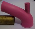
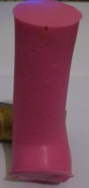
a product called "pinky-sil" which is a skin safe moulding silicone that you could use to mould body parts / orthotics / dental work, two parts which you mix together 50/50. Very pliable when cured and elongates easily without tearing so you can work it out of the port easily, I've even cast port and runner together as one unit several times... really helps with a visual representation of any port to manifold mismatch.


portmoulds 034.jpg
20191001_104319.jpg


SteveC
 
bowl depth and the port roof height, you need to give it a larger bowl volume and raise the port roof more
Steve, for the sake of understanding clearly. Do you mean the roof height more in the area I've circled in red, or circled in green, or both? It's difficult to illustrate what I mean on a flat photo, but basically I'm talking about the height of the bowl vs the height of the port, or both. Thanks

209DC496D3CB.jpg
 
Steve, for the sake of understanding clearly. Do you mean the roof height more in the area I've circled in red, or circled in green, or both? It's difficult to illustrate what I mean on a flat photo, but basically I'm talking about the height of the bowl vs the height of the port, or both. Thanks
Both.

If Jepp had have removed the guides entirely I could give him a suggested depth measurement based on the guide bore length, but he's simply pushed the guides "up" so that measurement won't work in his case.

If you look closely at the port moulds you'll see that the port is not a steady taper down from the 40mm opening at the carb manifold face to the 36mm or so of the port seat throat...

Instead it tapers down by necessity to around 29.5 / maybe 30mm at most in the manifold, then stays at 29.5/30mm for a distance until about half way along the port in the head (the point of minimum CSA) then it begins to widen out again... the taper down speeds the air velocity, the constant CSA for part of the ports length maintains this velocity (what DV calls "the energy bucket") and then the port lifts and widens to slow the air down before the turn (so the airs mass can make the turn better) ... but slowing the velocity also increases the pressure behind the valve, this is what we want to achieve, turning the kinetic energy of the airs motion back into pressure energy as it reaches the turn behind the valve.

SteveC
 
The head porting and combustion chamber is looking good.

The new guides look like they stick out the cam side of the head a bit too far... it could just be the angles of the pictures, but if they are too far out then you'll have issues with the spring retainer hitting the stem seal.


SteveC
 
Last edited:
Thanks everybody. I'm still trying to find time in my days to write up a full update to go along with the photo dump. It's been a long process but it sure has been amazing to have everybody's input and advice throughout the build.
 
The head porting and combustion chamber is looking good.

The new guides look like they stick out the cam side of the head a bit too far... it could just be the angles of the pictures, but if they are too far out then you'll have issues with the spring retainer hitting the stem seal.


SteveC
You're absolutely right Steve. The head is actually back at the machine shop currently having the guides pressed in further. When I initially brought it home and did a quick assembly to check my final cc volume, I also noticed they were too proud. I measured the distance between the top spring retainer and top of the valve guide and it was not enough clearance for the amount of lift on my cam.
 
Both.

If Jepp had have removed the guides entirely I could give him a suggested depth measurement based on the guide bore length, but he's simply pushed the guides "up" so that measurement won't work in his case.

If you look closely at the port moulds you'll see that the port is not a steady taper down from the 40mm opening at the carb manifold face to the 36mm or so of the port seat throat...

Instead it tapers down by necessity to around 29.5 / maybe 30mm at most in the manifold, then stays at 29.5/30mm for a distance until about half way along the port in the head (the point of minimum CSA) then it begins to widen out again... the taper down speeds the air velocity, the constant CSA for part of the ports length maintains this velocity (what DV calls "the energy bucket") and then the port lifts and widens to slow the air down before the turn (so the airs mass can make the turn better) ... but slowing the velocity also increases the pressure behind the valve, this is what we want to achieve, turning the kinetic energy of the airs motion back into pressure energy as it reaches the turn behind the valve.

SteveC
Steve any chance you could give that guide depth measurement as I have the guides out on mine guide length with guide bore step seems to be 40mm with guide step being 10mm is it as much as 10mm your deepening the bowl?
 
Steve any chance you could give that guide depth measurement as I have the guides out on mine guide length with guide bore step seems to be 40mm with guide step being 10mm is it as much as 10mm your deepening the bowl?
Tipo head, guides out, short side about 20mm, long side about 27.5mm.

Yes, it is as much as 10mm added to the bowl depth/height... as I keep saying it's the bowl depth and "fullness" of the bowls width when modified that makes all the difference, look closely at the port moulds and see how vertical / straight the bowl sides are.

Lift the roof, but leave the floor alone -don't even bother smoothing it off -

Start at the guide area of the bowl, DO NOT start at the manifold face - that should be left until the absolute last when you have the manifold pinned and you're doing the head to manifold port match.

SteveC
 
Back
Top