Mlott
True Classic
GM single wire alternator?
Ok, iam showing my ignorance on this topic.
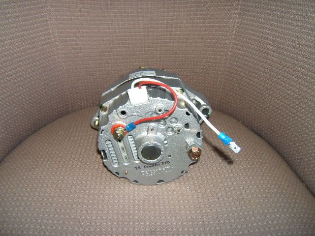
But would it be possible to use a single wire,self-exciting gm alternator.
like this one from eastwood
eBay: http://pages.ebay.com/motors/link/?nav=item.view&id=360794916334
https://www.youtube.com/watch?v=wPe6QzrNM2Q&feature=youtube_gdata_player
Ok, iam showing my ignorance on this topic.
But would it be possible to use a single wire,self-exciting gm alternator.
like this one from eastwood
eBay: http://pages.ebay.com/motors/link/?nav=item.view&id=360794916334
https://www.youtube.com/watch?v=wPe6QzrNM2Q&feature=youtube_gdata_player