Coolant Pipe Rework Surprise! Pipe Maker?

Alright. Pipes are ordered. Shoudl be only couple weeks turnaround. I'm stuck off my feet for another week with the foot surgery recovery, so not much I can do besides plan my basic approach to the tunnel reattachment at this point.
oh I dont want to be in your house during this "off your feet" time. Seeing your projects I am sure you will be wound up ready to do things in a day or two! let alone in a week!

Odie
 
oh I dont want to be in your house during this "off your feet" time. Seeing your projects I am sure you will be wound up ready to do things in a day or two! let alone in a week!

Odie

Yeah. It's rough - I've only been able to get up & move around (minimally) the last couple days. I'm going nuts. Can't work on the car, can't work on the house and my students are driving me nuts with their senioritis, getting them to submit their final projects for the year is making me blow a gasket
 
Here are some of the photos that belong in my "over-engineered structural SS tube tunnel" post, but looks like you're eager to go and I think these photos will help you a lot Carl.

This first set is before I pulled out the old tubes so you can see placement. The inner/hot heater tube connects to host on the passenger side of the tunnel under the hand brake. There are 3 (IIRC) places this is spot welded with brackets as it follows the passenger side tunnel up to the heater.
View attachment 7581 View attachment 7582 View attachment 7583

The return line runs down thru one of those oval cutouts (no plug here Rodger!) and next to the radiator coolant line tubes. It's a pretty good size hole.
View attachment 7580 View attachment 7577 View attachment 7575

Front to rear, Jeff is thinking you could run them on top of each other and exit that way. Yeah, probably. It is tight and I even added a little more room on my setup for some extra vertical structure in the tunnel wall as well as needed some room for my brackets, but you could probably do it.
View attachment 7579 View attachment 7577

I think the only thing that will be difficult is routing both of the hard heater lines around towards the engine bay.

Hope this helps.

Darin - do you have additional pics of how you have set up your revised tunnel cover? I'm trying to decide how I'm going to address mine.
 
which parts are you interested in? I'll post more pics and a fuller description of what I did, why I did it and what I was going for.
 
which parts are you interested in? I'll post more pics and a fuller description of what I did, why I did it and what I was going for.

Thank you, Darin
Mostly how you have handled the cover design & attachment to the side sections - I can see the side panels, but even those if you could post the pic rather than the thumbnail so I can zoom in for detail. I just can't decide which way to go. I am leery of cutting off the entire tunnel, as there is no rust at that seam, and I know that there are at least 3 panels welded together at that junction. If I can make a cover/inset for the tunnel that seems like it would be the most direct, but maybe that's just wishful thinking. So anyway, the more reference data the better, so whatever you feel like sharing.
 
Sure. First, regarding the "thumbnails" - they can be clicked and made larger, but I'm guessing thats somewhat difficult on a mobile device so I'll go back to my Project Overkill: Chassis thread and edit those posts to show a full size pic instead of the thumbnail.

Regarding the design of the lower tunnel, I did it in 3 parts - two vertical spars of steel shaped and welded to floor parallel to the joint for the floor and upper tunnel part and the third bit is a removable cap made from sheet stainless steel bent at a metal shop to fit over the spars. Remember, I did this specifically because I wanted the lower tunnel to be accessible/removable because I'm dumb that way. The method I used to put it together was painful and in retrospect there is a better way. I'll describe the way I did it first then discuss how I'd do it again.

The wrong way (how I did it) was to cut the steel spars to shape following the shape of the floor where the seats are. Next, I welded that in. Then I bent the SS cover to fit over, drilled holes for the bolts in the cap then installed and drilled thru the spars. That was the first difficult part as there isn't actually good room to fit a drill with the floor forward of the seats being in the way (see this pic). I have an angle drill and did manage to make it work out. Next, I needed to put weld nuts on the inside of the spars. I really didn't want to just weld them in then hope nothing was misaligned so I put a small bit of adhesive (expoxy) on the weld-nut where it wouldn't be welded, stuck all of them up quickly then bolted the cover on. Let it dry, remove the cover then weld the nuts. Worked well but a pain.

The better way to do it would be to cut the spars out, maybe tack it on, drill a few holes for the cover and affix it and cut the tacks. Take the whole thing to the bench, drill all the other holes, bolt up all the weld nuts with it all together and finish weld on the welding table. Finally put the whole thing back on the chassis and finish weld.

An even easier method would be to not use SS for the cover, just steel and weld it up instead of bolt it. If you are comfortable doing a corner joint on your car while on your back you could just use flat stock and weld it up.


Here's some pics of the tunnel cover removed.

IMG_5141.jpg


IMG_5142.jpg
 
Nicely done. I like the idea of having a removable cover. SS isn't easy to work with but yours came out great. ;)
 
The wrong way (how I did it) was to cut the steel spars to shape following the shape of the floor where the seats are. Next, I welded that in. Then I bent the SS cover to fit over, drilled holes for the bolts in the cap then installed and drilled thru the spars. That was the first difficult part as there isn't actually good room to fit a drill with the floor forward of the seats being in the way (see this pic). I have an angle drill and did manage to make it work out. Next, I needed to put weld nuts on the inside of the spars. I really didn't want to just weld them in then hope nothing was misaligned so I put a small bit of adhesive (expoxy) on the weld-nut where it wouldn't be welded, stuck all of them up quickly then bolted the cover on. Let it dry, remove the cover then weld the nuts. Worked well but a pain.

The better way to do it would be to cut the spars out, maybe tack it on, drill a few holes for the cover and affix it and cut the tacks. Take the whole thing to the bench, drill all the other holes, bolt up all the weld nuts with it all together and finish weld on the welding table. Finally put the whole thing back on the chassis and finish weld.

Thank you - the problem with the thumbnails (on my Mac) was that when I enlarge & try to zoom in, the image tends to 'skip' away from my cursor, so hard to look at a specific element. Anyway, the issue I saw looking at my floor is the one you describe, where the angle of the floorpan obstructs drilling. The further problem with retaining the stock verticals is the reinforcing ridges will interfere with the cover fitting flush. I still can't decide which way I want to go, besides that I don't want to weld a cover on laying on my back at any time between now & late spring when temps are back up in the high 60's.

Thank you for posting all the detail pics. Gonna have to ponder this one awhile.

EDIT: I looked at my tunnel pics again, the ridges are only in the lower surface, so I think just making a cover like yours is my best bet. I will use rivnuts set in the verticals

IMG-20200914-161417.jpg
 
Last edited:
The new BMRS stainless steel tubes installed. I removed the old tar strips and slipped sections of 1 1/4" Dayco radiator hose over the flanges on the ends of the tubes to isolate them inside the box. One on each end of the pipes should be sufficient. Now I still need to locate a local source for the panel bonder and an applicator gun. I plan on using clecos' to hold the tunnel in place once I apply the glue then replace them one by one with screws. No more than 12 screws placed along the borders of the box should hold it until the panel bonder cures. The dayco hose number is shown just in case anyone is having trouble locating a 1 1/4" hose.

View attachment 9717

View attachment 9718
May I ask what this cost to replace all the pipes with stainless including the bends please ?
 
Here is a pic of the BMRS stainless tubes installed in the original tube cover. The spot welds were drilled out. (It's not hard to do. ;))
coolant pipes and box.jpg

If you don't ask for a modification BMRS will place the drains at the bottom of the tubes. Fiat didn't put them there, and I didn't want them to do that on the tubes I use on a lowered car.
C coolant tubes edit.jpg
It was no charge to modify the position of the drains, but you've got to specify where you want them to be.

Website: https://bmrs.net/
Here are some of the details from my last order with them.
01/22/2018
PHONE: 704-793-4319
FAX: 704-793-4321
Brown & Miller Racing
Solutions, LP
4005 Dearborn Pl. NW
Concord, NC 28027

Mike Hynes
$235.00
0001 LWT-T003 X 1/9 Right Tube 1.25" x .049 SS
$235.00
0002 LWT-T004 X 1/9 Left Tube 1.25" x .049 SS
$0.00 Modify Drain Locations (See Rick)
0003 LWT-T005 X 1/9 .625" x .049 SS Water Tube

TAX:
TOTAL:
SUBTOTAL: 470.00
0.00
470.00
NOTES:
TOTALS FOR SALES ORDER : 235462


There are other solutions, but IMO this is the best repair.
 
If you don't ask for a modification BMRS
I seem to recall their "standard" design also has a odd size diameter at the inlets/outlets? I believe that was specified by Bernice back when she contracted with them to create these pipes, to match her specific race car needs? But I'm not certain.
 
I seem to recall their "standard" design also has a odd size diameter at the inlets/outlets? I believe that was specified by Bernice back when she contracted with them to create these pipes, to match her specific race car needs? But I'm not certain.
The tubes are smaller in diameter than the stock Fiat tubes/hoses. What BMRS does is add a "bushing" at the ends of the tubes to increase the OD of the pipes to match the Fiat sized hoses.
BTW - I have noticed no issues with smaller than stock diameter tubes. Makes me wonder how the SS pipes flow compared the the potentially rusted stock steel pipes?
 
So after all my research on the forum I decided to go with cutting off the existing pipes at the box ends followed by sliding in smaller SS pipes. Great plan...

But not knowing what was original on a '74 and what isn't I just discovered I cut off copper pipes(that aren't sitting inside of larger pipes) which I have since learned weren't original doh! And after looking down said pipes I realized that the large coolant leak at the back of the box was not coming from the copper coolant pipes! Insert many swear words here.

Which leaves the Heater Pipe, right? Has anyone experienced this pipe as the cause of the leaking coolant out of the box before?

Because now I'm at a crossroads. I can continue my rework as planed and plug off the heater but that seems like a lame thing to do on a 20k+ resto with a targa top or I can remove the f'ing box!!!

So can one disconnect and reconnect the heater pipe in the front from under the X with the box off or easily (oxymoron on an X1/9) from in the interior? Since the interior is 100% restored I do not want to mess with it again at all.

And lastly does anyone know the company that makes the pipes to fit as seen in the image below? My pipes are toast as a templet now.
View attachment 7508

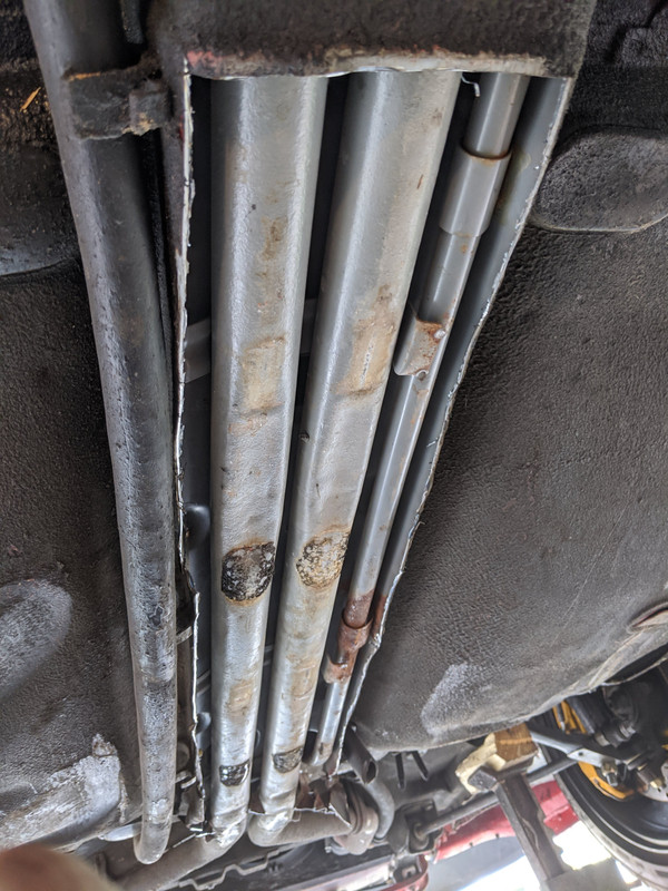
Oh and I only have this much area under the X to work.
View attachment 7509

Thanks, Carl

PS. I know the wing is on backwards :)
Carl,
TWO things...
1. the leak is probably the heater core (tiny radiator) itself. it is IN the plastic housing of the entire vent system, under the dash. IF you have a Haynes manual, it tells you how to take apart the vent housing where the heater core lives and then you can get it out to test it. the OTHER possible leak is usually the heater control valve, but I believe that is visible and located outside the box so you probably can tell if it is the source of the leak or not. The plastic vent housing comes apart pretty easily (cept for the difficulty of laying under the dash are). There should be two metal clips (similar to the type used on distributor caps but larger) that hold the lower half in place, once removed, the lower half of the housing will drop and the core can be taken out. It might be able to be repaired but certainly can be replaced.

the SECOND thing... Im curious about your rear spoiler... I WANT ONE like that! BAD! lol. Is it a factory spoiler or did you get it somewhere else and if so... WHERE and for how much!? please let me know. BTW I love the COLOR of your car.. its lime green but a bit darker and more intense than the factory Green (unless its just your photo!). but is LOOKS VERY NICE!!!

Keith
 
Hi Keith,

Well I replaced ALL the pipes with SS and resealed the box to the bottom. Also replaced the heater core pipe which had definitive leaks at the flange. Even though no liquid has been put back in the system I feel secure that it is all good but will keep an eye on the core when liquid is back in. Thanks

Spoiler or wing? The '74 came with a green spoiler which I traded to another member who has since passed. And all his amazing X parts were to be sold off by his muscle car relative in a group lot. No idea whatever happened to the parts. I even made an offer on a couple unobtainable pieces but to no avail. If the wing is cast metal colored you are inquiring about I got it from Henk Martins. His site is https://www.x19partsholland.nl/. The wing is not to be looked at from beneath which on an X would be hard to do of course. One can see hardware and connections which I'm not a fan of but like I said don't look there!

Oh and that green with the black stripe is slowly being erased. The repaint will be a metallic lime green now.
 
The tubes are smaller in diameter than the stock Fiat tubes/hoses. What BMRS does is add a "bushing" at the ends of the tubes to increase the OD of the pipes to match the Fiat sized hoses.
Thanks, I knew it something along those lines. I seem to recall you can request them to be made in the correct diameter pipes.
 
Back
Top