Greg (in Conn)
Bertone curator - X driver
Wil is onto something but...
I don't think George is racing this Martini X though...
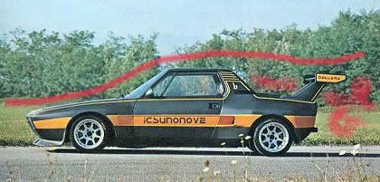
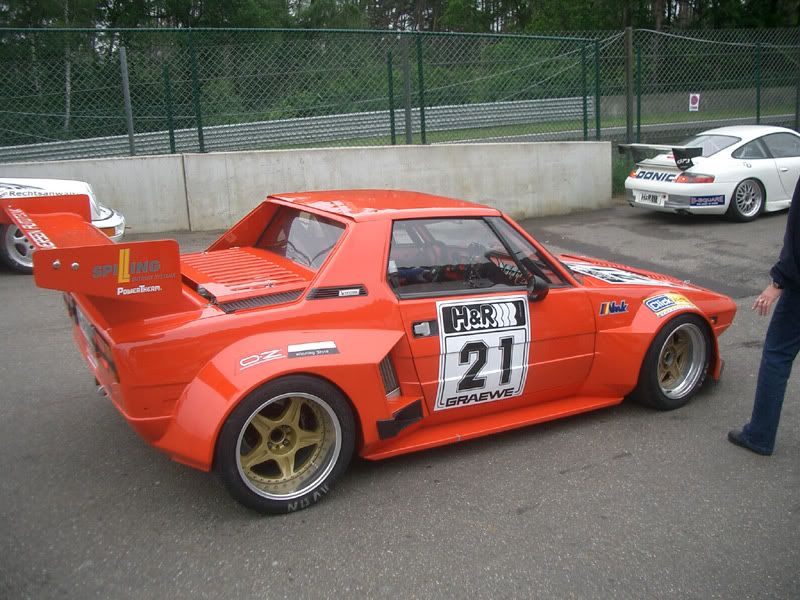
Here is a shot of Graversen with the same angle wing Wil is talking about...
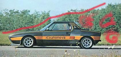
Although I have seen many more photos of him running the split wing below.
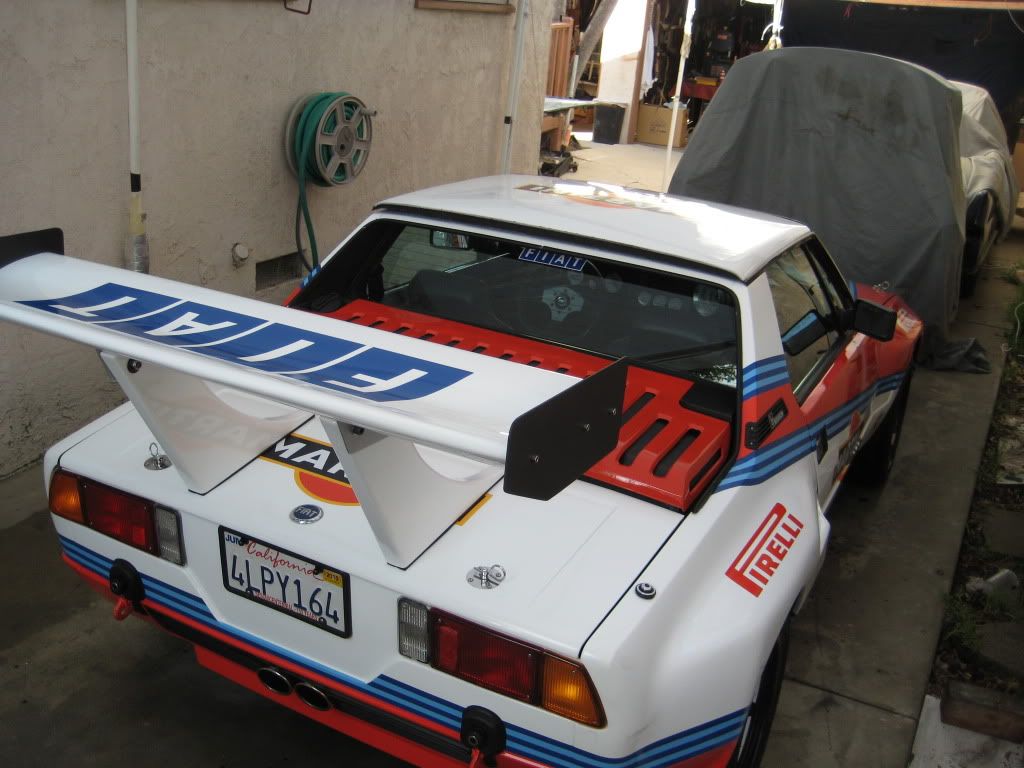
I don't think George is racing this Martini X though...
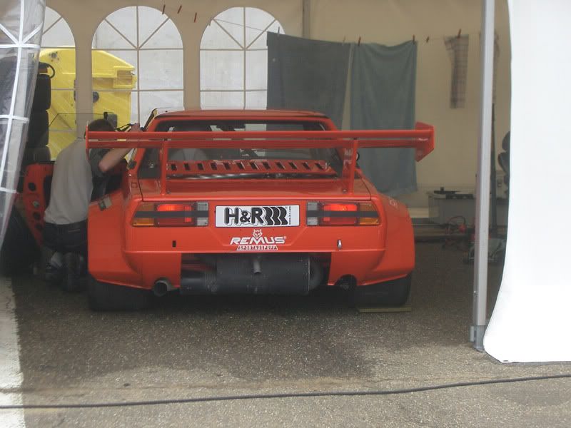
Here is a shot of Graversen with the same angle wing Wil is talking about...
Although I have seen many more photos of him running the split wing below.