Its not cool to have coolant pipe leaks!

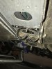
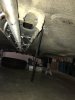
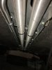
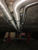
The AC lines are just like the heater lines; one of each is inside the car next to the upper tunnel and the other inside the lower tunnel box or under the pan next to it. I agree, seems like locating yours next to the tunnel box should work fine. They are small enough that the sides of the box will protect them. I'd recommend mounting them the opposite way from your concept drawing; with the tube up top at the corner of the floor pan and the clamp below the tube, just to get the tube as high as possible for maximum protection.

For the heater lines, I am going to try an experiment. Due to the climate where I live, heaters are very optional. Even if you drive the car year around, they might get used a couple times a year. And frankly I don't drive these cars much, especially not when the weather isn't "topless" conditions. Furthermore, when the heater is utilized it is on the coolest setting to keep from burning yourself up. But rather than eliminate the heater entirely (which I considered), I will attach the input/output lines to the large coolant tubes instead of off the head/engine. I realize this means the heater will only get warm water when the T-stat is open, but frankly the T-stat will be open shortly after starting the engine - even in the deepest part of winter here. Besides, with the stock configuration the heater does not get warm until the engine warms up any way. So no real difference for my needs. This allows me to completely eliminate the fittings at the engine and the long tubes/lines from the engine to the heater box. Instead they will connect into the large coolant tubes just in front of the tunnel, right below the heater box. A very short run up to the heater core/valve. This will be easy to do due to two things; 1) I will be using copper tubes to replace the large coolant lines so adding a pair of "tees" is no problem, and 2) I will be replacing the heater valve with one for a Mk1 VW so connecting the hoses will be simple. If it does not work, then it won't be difficult to cap the small tee fittings off the coolant tubes and go back to a more standard layout. We'll see what happens.
 
Last edited:
Thanks Ulix. Looking at the pics in your link, I've seen those before. They are heavy duty, much more robust than the regular T-bolt clamps used for turbo pipes, etc.. Indeed they will offer excellent clamping force. I also like the full coverage inside to protect the hose all the way around. And one Euro each (just over $1 USD) is an excellent price. I'll look to see what is available here in that style.
 
Oddly, when I looked for these online I found even the non-S/S ones were about $7 to $8 USD each (as you say, S/S is even more). Actually the listings just said "steel", but they did not specifically say they were not S/S. So maybe they were S/S. I didn't look to extensively. But either way that was a great price for yours; even regular cheap "worm" clamps are more than that here.
 
I've decided to go with Stainless tubes due to the potential for Copper corrosion. I couldn't reconcile doing all that work and then having Galvanic corrosion ruin it all. I've cut off the bottom of the tunnel, will replace the tubes with the Brown & Miller SS tubes then take it to my welder and have the bottom tunnel welded back up. I spoke to B&M, the tubes will be ready in one week. I just have to figure out the way in which i'm going to support them in the tunnel. I have a few ideas but have some time to figure it out.
 
Ricardo, Thanks for the info. I'm glad that you've had such good luck with your repair, you do some amazing work. I also didn't want to have to do all the sweating of pipes and beading of the ends. I'm having the drain plugs installed as well on the 304SS pipes and I wanted it as close to the original config as stock. I have the money and at this time of life my time is worth more to me than the alternate fix. I appreciate your input!
 
I finally completed the install of the Stainless coolant pipes. Trust me this is not a job you want to go into thinking this is going to be easy. I don't have a lift so I was on my back on the cement floor in December in New England. Needless to say i know how a Popsicle feels. First few picks show how the pipes arrived from B&M. To recap I cut the tunnel off at the bottom corners leaving the welds to the undercarriage untouched. I will weld the bottom piece I cut off back to the tunnel thus reinstating its original design. My issue that I needed to tackle first was the hangers. As you know they are integral to the original box design so in cutting off the bottom of the box I had to cut them off as well. I designed replacement bolt on hangers by fabricating flat bar into brackets that spanned the width of the tunnel then drilled through the side of the remaining box walls that matched the holes I drilled into the brackets. I sourced some stainless steel "P" brackets and had them welded to the brackets. Finally I had a stainless steel bolt welded in between the P brackets. This bolt would serve to fasten the P brackets to the flat bar bracket thus supporting (Hanging) the Stainless coolant pipes. The biggest challenge was aligning the fabricated brackets so that they matched up along the length of the pipe while it was in the tunnel. I originally planned to have three brackets installed but that became problematic as the dimensions within the tunnel did not allow for easy installation and alignment. I also felt that three brackets were overkill. I had to make some adjustments to the design of the brackets along the way so they are different in the front of the tunnel vs the back of the tunnel. The front bracket attached from the side walls of the tunnel while the back bracket attached downward from the e'brake access hole in the cabin. There was a fair amount of design work on the fly but it came out secure and robust. I can now fill the coolant system and start this middle aged girl up just in time for the snow to fly!!!
 

Attachments

  • IMG_6995.JPG
    IMG_6995.JPG
    149.1 KB · Views: 181
  • IMG_6996.JPG
    IMG_6996.JPG
    202.3 KB · Views: 177
  • IMG_7017.JPG
    IMG_7017.JPG
    130.5 KB · Views: 192
  • IMG_7076.JPG
    IMG_7076.JPG
    146.2 KB · Views: 185
  • IMG_7079.JPG
    IMG_7079.JPG
    130.9 KB · Views: 191
  • IMG_7069.JPG
    IMG_7069.JPG
    109.8 KB · Views: 171
  • IMG_7072.JPG
    IMG_7072.JPG
    111.8 KB · Views: 189
  • IMG_7070.JPG
    IMG_7070.JPG
    185.8 KB · Views: 186
Excellent. Congrats on reaching the end in that part of the project.

Now to close it in
 
After reading all this, I really wonder what kind of market would there be for a replaceable pan out of stainless? I have done the removal and had a guy make one with flanges, for bolts...wonder if it would be worth the investment to have a few made and sell them...not looking to get rich, but the one I had made looks factory and fit like a champ, and made my life so much easier, lol...and it was CHEAP...so how many would want something like this under 100 bucks?
 
Nicely done.

Typical of what is involved to replace the coolant pipes, no fun at all. This is a very reasonable way to get this task did. Only concern it the welded SST threaded stud to hold the brackets in place. Welds can be brittle, crack over time, vibration, loading then break off. If the cover is welded in place replacing that broken mounting stud will be a significant task. Alternate to welding is to used LOTs of small threaded fasteners.

As for a SST pan, this could be made up a a kit. coolant tubes from B&M, a replacement pan with mounting holes and end caps.

Bernice
 
I appreciate all of the positive feedback, especially from this community. I'm trying to restore this beauty with my best effort, best materials/parts and advice available. Sometimes it takes a bit of "Yankee Ingenuity" to get 'er done, odd for me to say that as I'm a Red Sox fan, but it is what it is :D. I think with this repair out of the way I'm finally seeing the light at the end of the tunnel (started Sept '15). I'm sure there will be an oil leak and potential water pump etc..issue ahead but that's wrench tuning stuff i love to do. Besides I could be driving it while tackling those repairs!

@Bernice are you refereeing to the reattachment of the bottom of the box with LOTS of small fasteners? Will that be strong enough to achieve the OEM design structural integrity of the box?
 
this could be made up a a kit
Also include the mounting straps/clamps to secure the tubes in place.


Will that be strong enough to achieve the OEM design structural integrity of the box?
I'm sure she'll agree, yes it will be strong enough. Same type of construction as many aircraft utilize. Before carbon fiber became the norm for Formula1 chassis, they made them with aluminum sheets riveted together. Same technique - lots of fasteners along the seams of two panels.
 
Don't forget to include applications for part time employment as a second job to pay for the complete kit!
Agreed, nice work.
 
Yes, this is the same problem in the 74' after some hack off the bottom of the coolant tube box to replace the coolant tubes, then did not put it back together as OEM. At some point will need to make a folded metal cover and apply a pile -O- NAS1801-3 screws and nutplates to fix this.

Awful lot of aircraft and race cars held together by a pile -O- small rivets, screws, Hi-Loks and similar. These are often 0.19" or 5mm and smaller. Idea is to distribute the stress over a larger area. Welding is the most difficult means to creating a joint. It is not often appreciated how many things can go wrong with welding, yet so many use welding in the same way as hot glue for metal.

Bernice


@Bernice are you refereeing to the reattachment of the bottom of the box with LOTS of small fasteners? Will that be strong enough to achieve the OEM design structural integrity of the box?
 
Back
Top