Rebuilding a Series 2 Electrical System

Steve Thomas

True Classic
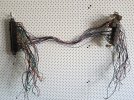
One of my 1980 Australian delivered Series 2 cars [Series 1.5 4spd, 1300] came with its electrical system in a milk crate. The other came with no electrical system at all...

As Delivered.jpg
Starting point is stripping the fuse box.
Relays and Fuses.jpg
Pulled the fuse block and relay mount bracket and hung them up. Interesting. There are a fair few wires that go only from a fuse to a relay and yet are about 700mm long.
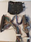
Fuse Box Loom.jpg
I will be taking the excess wire out - will go down to about 100mm from 700mm. The other thing I will do is re-route/re-lay the wiring at both the fuse block and relay group. The wires that come out of a fuse and go off to the car somewhere have to pass under the relay group. They should be on the bottom row of the fuse block so they can lay flat down on the tray. The wires that go from a fuse to a relay will be at the top on the fuse block end and the front at the relay end. The wires that run from a relay go off to the car somewhere will be at the back of the relays. It won't be as black and white as that - but those are the principles I will follow. The end point is less wire and much more space efficient packaging.
 
Last edited:
You'll also find wires that exit the fuse box area, join one of the main harnesses out to a section of the car, and wander around seemingly randomly before finally getting to its destination component....with lots of extra wire wasted in the process.

When I cleaned up the wiring on the current X project I ended up with a trash bag full of "spare" wire. And that wasn't a complete rewire, just clean-up and repair.
 
You'll also find wires that exit the fuse box area, join one of the main harnesses out to a section of the car, and wander around seemingly randomly before finally getting to its destination component....with lots of extra wire wasted in the process
Yep, can see that and I have started my excess wire collection :)

Which will be handy as there are places where repairs will be required so a bank of "correct" wire is a good thing.
 
About to start that. Think it looks a lot scarier than it actually is, as most are stand alone systems so they can be done one at a time.(tell myself that to control the fear)
To label the wires I printed labels on photo paper with exel or the like, cut them up slipped the labels inside clear heat shrink. Tried using a dymo label under heat shrink but the heat from shrinking the heat shrink made the printing run.
 
label the wires
My PO started with masking tape flags. Maybe they wrote something on them..... Time has taken its toll - the tape falls to dust when you touch it and any marks are long gone. But - its not too hard using the colours, the look of connectors and the relative positions of everything. Agree on the basic simplicity of separate systems. We are lucky, no FI and no seat belt warning idiocy etc. I am marking up the FIAT wiring diagram I have - minor error corrections and will post it in this thread.
 
My PO started with masking tape flags. Maybe they wrote something on them..... Time has taken its toll - the tape falls to dust when you touch it and any marks are long gone. But - its not too hard using the colours, the look of connectors and the relative positions of everything. Agree on the basic simplicity of separate systems. We are lucky, no FI and no seat belt warning idiocy etc. I am marking up the FIAT wiring diagram I have - minor error corrections and will post it in this thread.
Actually the FI is yet another stand alone set of wiring so it adds very little complexity to the rest of the system. The biggest difference is the addition of another main power wire plus the standalone harness.

If you can, make a large copy of one of the higher resolution wiring diagrams. Some of printing services can make them very large, like 4’ wide and 10’ long (or longer due to printing off a roll).
 
Despite being a child from an earlier age, I am using a cheap large screen telly as a display for a laptop. Big enough to be able to read the whole thing :)
The nice thing about a large print is one can annotate it… permanent marker doesn’t come off a screen very well :)

Having a large display in your man cave with modern quality displays is a great thing when working on small fiddly bits. The nice thing is no grease on your manual pages :)
 
Regarding stand the alone wiring layout. Unfortunately there are also a lot of "non-stand alone" things, like piggy-backed power wires, daisy-chain branched circuits, etc, that can confuse the otherwise isolated systems.
 
Here is a question. The wiring schematic I am using indicates connectors. Generally pretty accurately. But in this image below there are two 12 pin connectors that just do not appear to exist [bottom right of image]. Their position on the schematic implies that they would physically be behind the seats somewhere? Anybody seen them?
1704859729077.png
 
Here is a question. The wiring schematic I am using indicates connectors. Generally pretty accurately. But in this image below there are two 12 pin connectors that just do not appear to exist [bottom right of image]. Their position on the schematic implies that they would physically be behind the seats somewhere? Anybody seen them?
View attachment 80500
Could you show it a little less closeup? No there aren’t any primary connectors behind the seats.

I can’t say I have ever seen this particular diagram, it is unusually detailed and clear.
 
Back
Top