Rebuilding a Series 2 Electrical System

Regarding stand the alone wiring layout. Unfortunately there are also a lot of "non-stand alone" things, like piggy-backed power wires, daisy-chain branched circuits, etc, that can confuse the otherwise isolated systems.
That is true many will draw power from other common actives,but they don't have to be if you are happy to run more wires. Cost is unexceptionable on a production run not a problem for one car. What I was getting at is that one system is not relying on the operation of another as is with a modern computer car.
 
Yes, the best of the many I reckon - it is a schematic that captures the harness rather than the logic. Came from https://x19.com.au/manuals.html

Too large for me to upload here directly.
Thank you. Some great info at that site.

Greatly appreciated.

I can pull the wiring diagram out as a high res PDF, JPG, PNG etc if anyone wants it.

Going back to the original question, to the best of my knowledge I have never seen those additional connectors in any X. Perhaps in the AUS market they added some additional connections or could it be a feature of right hand drive cars? Or is it just a phantom graphic feature they used as a break akin to the bar with the numbers?
Everywhere else they use that "connector" graphic in 1, 2, 4 6, 8 etc versions, I have a real connector with pins as per shown. I suspect that the 12 pin connectors were design intent that got cost reduced out :)
 
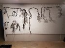
Got the whole harness sorted and pegged up sort of logically. For scale - the pegboard is about 1.8m high by 3.6m long [6 foot x 12 foot]. Headlights to the left and tail to the right. Most connections identified [bagged and tagged].
Harness on Pegboarf.jpg
Next step is to roll the shell in from storage and start working thru the routings and actual connections to components. Plan to start with the tail light loom. The whole harness was cut into sections to ease removal by PO and in most cases, I will insert a connector [or so] to rejoin.
 
My PO started with masking tape flags. Maybe they wrote something on them..... Time has taken its toll - the tape falls to dust when you touch it and any marks are long gone. But - its not too hard using the colours, the look of connectors and the relative positions of everything. Agree on the basic simplicity of separate systems. We are lucky, no FI and no seat belt warning idiocy etc. I am marking up the FIAT wiring diagram I have - minor error corrections and will post it in this thread.

That's a great idea. I started editing my wiring diagrams to reflect my mods, like adding relays, here's an example of the modified wiring diagram for my Coupe:

1705007610318.png
 
I read this as "moods" first time :) I like the colours too. I will do that as well.

Last weekend I had to get into my X's fuse box because my power windows quit working. There were some mods in there that a younger me had done that I had totally forgotten about, specifically the addition of relays for the power windows. I had to reverse engineer what I had done to troubleshoot.
 
Last weekend I had to get into my X's fuse box because my power windows quit working. There were some mods in there that a younger me had done that I had totally forgotten about, specifically the addition of relays for the power windows. I had to reverse engineer what I had done to troubleshoot.
Been there. "What idiot did this?...oh, right.."
 
I know my s1 car has larger connectors in the spare tire well. I think they're only 6's though.
Cool! From the 78 drawing [Australian Series 1] - looks like an 8 and a 12. Kinda confirms my thinking that they were a cost reduction deletion that was not documented...
1705015109177.png
 
Cool! From the 78 drawing [Australian Series 1] - looks like an 8 and a 12. Kinda confirms my thinking that they were a cost reduction deletion that was not documented...
View attachment 80534
Only thing that makes me wonder, what about the 2 into 1 wire connections? Is there some kind of butt splice bound up in the wire bundle? Or did the 2 wires get extended to their final destination?
 
2 into 1 wire connections
Done properly - at places like fuses or the coil, there are dual male spades and each of the two is terminated properly. In other places, the two are crimped together in a connector. Where the schematic says two go in and one comes out - that is exactly what happens :)
 
Yes, I have seen that many times. But the connector you were asking about had some of these 2 to 1 connections. If the connector doesn't exist, where are those 2 to 1's?
 
Yes, I have seen that many times. But the connector you were asking about had some of these 2 to 1 connections. If the connector doesn't exist, where are those 2 to 1's?
That is an excellent question! A really excellent question! I will see what I can find :)
 
OK - ref snip below. The 24 wires inside the red box are bundled and run together in a long section of loom. Well long enough to reach from the engine firewall area to up under the dash above the fuse box. My assumption that I was looking for 12 pin connectors [blue arrows] near the engine firewall was wrong - in fact my 2x12 pin connectors would have been above the fuse box as others have suggested. I still don't have them :). I confirmed that I should have them by wire colour counting and I have checked back along each wire to look for any kind of 2 into 1 joint. There aren't any and the number and colours of wire match perfectly on the left and right hand side of the connectors I don't have. Spoke to the PO and apparently the previous PO already had the fuse box area in a state of disassembly in the footwell trying to resolve a "won't start" issue. Car had been standing for 15 years and engine was seized with water in front 2 cylinders. Anyway, those 12 pin connectors [both sides] have been cut out of the harness and lost.

1705207400340.png
 
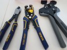
And to ensure I cannot blame my tools for my workmanship - some good tools. Wirecutter, Stripper and Crimping tool. Good brands being Irwin and Teng.
Tools.jpg
 
Back
Top