Scuderia Ferric Oxide

@Paul Valente they are some very interesting solutions.... complex , but interesting.

I spent some time today doing some measuring and figuring, I was stuffed as why my virtual LCA length by calculation / layout on the floor and Gregs measurement were so different. That's why I re drew my layout again, and tried to make an allowance for the caster offset etc as I was drawing everything in 2D.

So today I made a gound line, a thick piece of 6mm plate steel (which is for the roll cage mounting plates) and put it under the front of my car (which is on a table) so I had a level ground line point to measure down to.

As soon as I started re assembling the suspension and checking caster angle etc, and moving the wheel thru a range of motion I realised several things.

in 3D as the wheel moves up and down, if you look at the wheel side on, the centreline doesn't move straight up and down, due to the 6 degrees of caster (and possibly the strut inclination as well) that point travels thru quite an arc, certainly not a straight up and down line.

The same can be said for the ball joint position, but not only does this point move thru space in an arc in the X axis, it also moves thru an arc in th Y axis...so as you lower the car, the virtual LCA length gets longer (until the pivot point axis' are level with the ground line)

My measurement when I laid out the front on plan of pick up points/pivots was done using standard ride height (error number 1) based on 145/80/13 tyres. we don't intend to have the lower control arm angled down at all, so there is one gain to the virtual length over my layout 240mm virtual LCA measurement measurement.

next was small error number 2, I plotted everything at zero camber to make it easy for myself drawing right angles evrerywhere.

Next is the big error number 3, I did some trigonometry based on a few rough guess numbers and added 5mm to my layout LCA figure... today I had carpenters squares and string lines pulled tight going in all directions and was able to get some real numbers..

with suspension assembled (a rim but no tyre fitted) I was able to set my suspension (no springs) at ride height (this is all based on standard top pivot position too BTW, I just used a standard top mount bolted to the standard turret for this) and plot down to my ground line plate with some reasonable accuracy as there was quite good access, and my trigonometry additions and adjustments (using the correct numbers) concurs with what I plotted out within 1mm

So I think a very safe number for virtual LCA with the control arm sitting level and the strut caster / camber is allowed for is 265.5mm (+-0.5mm)

The other thing that sort of stood out playing with the 2D programme was the importance of tyre aspect ratio on ride height settings, mainly because it affects the vertical position of the wheel side pivot of the LCA, (the ball joint) relative to groundline.

This got me thinking about the next most effective change to make to try lower the chassis / maintain good geometry (keep the LCAl level between the pivot points. would be to try alter the ball joint pivot point to position it lower relative to wheel centre line...so thats the next thing to look at., as well as making the LCA adjustable for length, as a litle modelling shows extra LCA length could be a good thng (like all things to a point)

But given the limitations of the online 2D modelling, it still (even with some incorrect data to start with) does show trends that occur when you move certain points around, which was mostly the object of the exercise in my case, and sort of served it's purpose for now.

For example there is a relationship between the upper pivot height and the pivots distance from centreline that definitely has a "sweet spot", and that sweet spot changes depending on the ride height setting... certainly something I probaly wouldn't have worked out so easily without playing with the online 2d model

but to get into any true development of the chassis I think Steve H is absolutely correct in that you need (really) good data and a good 3D modelling programme to get a true picture of what is happening - not just with camber curves and roll centre position, but what really matters which is the weight transfer across the chassis / tyres.

Fortunately a friend of a friend (who I rang today to get him to ask) has a 3d suspension modelling programme, so I'll find out what he has soon and see if he's keen on giving me a hand to map / plot things properly too.

SteveC
 
Last edited:
Some interesting discoveries there Steve.
Do you think it is worthwhile me checking my suspension movement without a spring in place? Wondering if I could get any measurements that I could put in to the 2D model to get an idea of where the RC ends up with 2 deg of body roll.
With my standard strut towers I don't think I will be able to move the top mount any more than another 10 to 15 mm, I have coilovers, but still using original rubber top mount. It looks like it is definitely worth limiting body roll to no more than 2 deg, so I will be getting stiffer springs (currently 2.5 deg roll).
Will be interesting to see what you find if you can get hold of the 3D modelling program.
Cheers
PS I also put in 10mm of tyre sidewall compression, makes quite a difference.
 
Last edited:
More suspension figuring and measuring this afternoon after work.

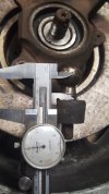
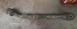
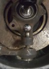
Seeing as the outer LCA pivot position determines how low the chassis can be set and still maintain good geomertry, today I pulled a lower control arm apart for two reasons..., to get an accurate measuremnet to the pivot centre point, and to see if the ball and pin could be replaced with a spherical joint to allow it to be repositioned.

It was quite simple on the OE joint I chose, I simply ground away the rear side until the cup was almost gone, and then gave the pin a sharp whack with a hammer and the joint came apart. I wasn't fussed about trying to save it, the plastic cup was a bit worn and the joint was loose as the boot had been torn.

measuring the true point in space of the pivot was then pretty easy.

While I had it on the bench I double checked the other required measurements for the 2D modelling programme, so now I think I finally have numbers that are truly representative.

I measured/ eyeballed the ball joint pivot at 90mm offset from the wheel flange line before, measuring back to the machined face for the brake caliper, and then a second measurement to the wheel flange face gave me 89mm

I got a out a new front strut, mounted it to the hub and measured up and scribed a line along it's centreline, and with a set square was able to mark off the wheel centreline to strut centreline and measure back to the wheel flange face, 130mm is what I measured, my original eyeball was 125mm.

The ball joint pivot to wheel centreline, I was using 67.5mm, Greg eyeballed 70mm, and without pulling a joint apart it is pretty hard to guess where the pivot centre is... when you have the ball only there to measure it's simple... 72.5mm. (which is great as the lower this is to the ground the better for the camber curves and ride height)

So if anyone wants to model their ride height setiings / tyre sizes and see what's happening with camber crves and roll centres (approximately) I think these numbers are close, and will get even closer once I do a little math to work out the relationship between the strut attachment bolts distance from centreline as we pivot the strut here to set our camber as that distance obviously changes as we tip the upright in/out.

I think replacing the ball / pin with a spherical bearing and moving it 57mm downwards / 8mm closer to the wheel flange line is an option I'm going to explore

Not much to see, but everyone loves pictures.

20210322_162917.jpg20210322_162944.jpg20210322_172343.jpg

I'm thinking of inserting something like this, an ABYT8 or an ABTY7, high angular spherical bearing designed for motorsport application
abyt10.jpg

ABYT8
Imperial:
0.500" Bore x 1.1250" outside diameter x 0.401" Race width x 0.937" Ball width.
Metric:
12.70mm Bore x 28.575mm Outside Diameter x 10.19mm Race width x 23.80mm Ball width.
and can handle 20 degrees of movement

ABTY7
Imperial:
0.4375" Bore x 1.00" outside diameter x 0.345" Race width x 0.875" Ball width.
Metric:
11.112mm Bore x 25.40mm Outside Diameter x 8.76mm Race width x 22.22mm Ball width.

with a 57mm ball joint drop (allowing 8mm movement of the ball joint pivot towards the wheel flange line with this drop) and moving the upper strut mount bolt 1.5mm closer to the strut centreline, 60mm inwards shift of the upper pivot point, and 40mm upwards on the upper pivot point... and 60 series 14 inch wheels ...

all these changes put the car 74mm - almost 3 inches lower than a standard car (standard is inner pivot at 229 above ground line, this is 155mm.) and it looks like it doesnt lose camber or vertically shift the RC too badly

The only thing is I'm not sure if there is enough tyre clearance to the inside of the strut tower

X19 SteveC 60in/40up 57mm drop 1.5mm in strut

the bonus is that ball joints are lemons dollars free spend, it doesn't count to the build total :)


SteveC
 
Last edited:
Is 20degrees sufficient misalignment? I guess it just seems low compared to how much the stock balljoint pin can pivot/swing when not installed.

Also, I wanted to know how you are bracing the chassis to offset the targa/sail structure removal?
 
Is 20degrees sufficient misalignment? I guess it just seems low compared to how much the stock balljoint pin can pivot/swing when not installed.

Also, I wanted to know how you are bracing the chassis to offset the targa/sail structure removal?

It's the largest angle sperherical joint available, and using the 2d model, at 50mm of suspension compression / movement upwards, the control arm goes from zero degrees to a 10 degree angle, so I think it will work,. his mod probably wont fit into 13 inch wheels so easily.

57mm is kind of the smallest change I can make if the spherical joint atttaches directy to the underside of the upright, as it's pivot is 1/2 of 23.8mm down from the top face... so lets say 12mm, the original ball pivot point is 25mm above the uprights mount, the upright is 20mm thick. 25 + 20 + 12 = 57.

If I do this up front, it makes sense to me I would also need to do the same thing at the rear to keep the chassis anywhere near level.

If you look at the targa hoop, you'll find it contributes very little to the torsional ridgidity of the chassis. It's only real functon is roll over protection, and as i'm fitting a tubular roll cage to protect the driver, it becomes redundant weight.

It forms a trapezodal shape above the main chassis structure, but removing it from up above the window line I think hasn't really altered the torsional stiffness of the chassis, certainly no more than removing the underside water pipe channel / box section...

To improve the torsional ridgidity of the chassis - not because I've removed the targa bar - I am adding some bracing

1. on the right side of the passenger compartment to brace across the door opening, so from the right side base of the original targa bar hoop to the top of the door frame (more or less),

2. the drivers side will have a lower / smaller triangulation in the side intrusion bar that's mandatory.

3. The roll cage hoop is going to be also be attached to the chassis section that runs left / right behind the driver (where the "parcel shelf" is) which is normally a 3 sided U section which I've added a fourth side to to enclose the section to a boxed channel (which improves torsional strength by a factor of 3 from memory)

4. attached to more or less the middle of this section will be a diagonal tubular brace running forward to the top of the right hand door pillar (more or less) attached to the rail that runs left / right behind the dash.

these two bracing bars are not part of the main rollover protection, not attached to it, so they don't need to be made from the same thick walled tube. Basically I'm adding in a big triangle from the section under the back window, middle and right side , foward to the right corner where the under dash left / right brace and the door pillar meet. I think that will provide the greatest increase in ridgidity for the weight added

as well as any additional ridgidity provided by the hoop and backstays.

SteveC
 
Last edited:
Steve, just going back to your measurements, your 116mm from hub to lower ball joint x, what thickness of wheel spacers do you have against the disc to get this. I am trying to compare to my measurement but getting a bit confused about all the spacers you mentioned earlier.
 
I've got a 4mm steel spacer under the disc hat, to centre the disc in the caliper / bracket combination.

The disc flange thickness is 11.5mm (which I can skim down / remove weight and adjust my track by small amounts if I need to)

and I have a 20mm alloy spacer on top of the disc face.

So my standard wheel flange to strut centreline measurement is 130mm, add to this 35.5mm (I rounded down to 35) which gives me 165mm at this distance.

I'm allowing 1.5mm of change to this measurement for the camber change needed, so this measurement with the balljoint change is 163.5mm in the simulation.

The ball joint pivot to wheel flange I measured at 89mm.

By dropping the balljoint down by 57mm also moves this pivot point outwards, as the ball joint pin is angled to the wheel centreline, I have allowed 8mm of offset here.

Where the pin pivot is when in the original position is apporximately 35mm above and 5mm inward of the centrepoint of the tapered hole thru the upright, My pivot will be approx 22mm below the centrepoint of the tapered hole, so I allowed an additional 3mm outward movement of the pivot position, so now its 81mm away from the wheel flange centreline

add to this the 35mm of dics / spcaers same as the strut CL measurement, 35 + 81 = 116mm

SteveC
 
Last edited:
Ths afternoon I did a little measuring and figuring on the rear suspension.

If I alter the ball joint pivot height at the front, I also need to do the same thing at the rear, but it looks possible inside 14 inch wheels.

The height of the rear ball joint pin above the rear hub leg to which it attaches is approx 45mm from the centreline of ths leg. (These are all just approximate measurements as I still need to pull apart a rear ball joint so I can measure the pivot point height / offset easily and correctly. )It also uses a larger pin size / basically a 16/14 taper (unlike the front which is a 14/12 taper)

With the taller offset height and the thicker casting of the leg, the minimum shift I can see being possible is 70mm down, which will equate to approximately 12mm outwards as well.

Putting these measurements into the 2 model with my wheel and tyre sizes, (and at the moment just a good guess at the virtual LCA length based on track width) I get the rear roll centre sitting 40mm above ground line. Very similar shifts of the other points 55mm inwards / 40mm upwards move of the upper strut pivot (the same as the front with the 55mm ball joint drop -the front RC is 55mm off the ground) the lower inner pivot at the rear ends up just 140mm from the ground, so a 75mm / 3 inch drop from stock, the same as the front.

The only thing having the car this low it may create other issues, simple things like being able to get a jack under the car! the underside of the footwells is only 80mm off the ground (there is no undercar water pipe tunnel) so these are the lowest point of the car, normally about 150mm off the ground, so it becomes difficult to load onto a flatbed truck as it might belly out in the middle. Axle angle may be an issue?

It would be nice to drop the CG down 3 inches though

@Steve Hoelscher have you ever had an X19 a full three inches lower than stock?
any issues did you noticed / had to rectify if you have?
no matter how hard I try I can't get the rear roll centre down below 40 without the camber curve and RC shifts becoming less desirable and you were talking 25mm rear RC height? I think the biggest difference will be my 111mm sidewall height copared to your low profile slicks, so this might be some of the difference? 40 at the rear and 55 RC at the front still has the roll axis angled up slightly as desired.

this is my 2D model of the front and rear with the balljoint drop (55 front / 70mm rear) the front I think is quite accurate, the rear is still a work in progress (but I think close) ...

is there anything you can see that I'm missing?

X19 SteveC 55mm F / 70mm R pivot drop

SteveC
 
Last edited:
have you ever had an X19 a full three inches lower than stock?

This is an interesting question. Really, what I think we need to ask here is has anyone dropped the car 3" using suspension only, and not shorter tires, etc. My old race car had around a 3" drop (same issue with jacking and loading on a trailer) but most of that was through maybe a 1" drop in suspension and then the tires used (slicks, 8x13 which had a 20" diameter).

What is the angle of your driveshafts in this configuration? Somewhere on the forum is a conversation about trying to keep the geometry of the suspension travel the same when lowering the car otherwise the only thing which will happen is the camber will increase dramatically as load is put on a corner due to it being at the end of its suspension travel.

I am really excited to see how this turns out.
 
If you lower the car far enough you can hit the stock alternator mount with the right side axle. You might be able to mitigate the issue with an alternate/modified bolt/mount. Be sure to check it out before you go too far.
 
Steve, sorry I haven't kept up here but as I noted previously, I have a lot on my plate this month.

A few thoughts: I noted earlier on in this thread that the 14" wheels and taller tires will have an impact on ride height, wheel travel and roll center height. I'll get to those in a moment.

I have come to prioritized roll center height over the camber curve. This is because roll center height determines weight transfer, transition speed, how the car takes a "set" at turn-in and feedback to the driver. The limitations of the camber curve can be mitigated with static camber, total roll limit and tire choice. This explains why I run the car as stiff as I do and the 3.5 degrees of negative camber.

There is a practical limit to how low you can go. Wheel travel specifically (as opposed to suspension travel) can be a problem, especially in front. The top of the tire will hit the under side of the front strut turret and may be your limiting factor in how low you can run the front of your car given the relatively tall sidewall and 14" wheel diameter. For the rear, somebody already noted the alternator will foul the right side CV axle. I cracked an alternator case on my '80 model car at its first nationals. I also over-traveled the left side CV axle which damaged the cage and caused it to start binding.

On my MR2 I was able to get the car low enough that I was bottoming the front cross member and dragging the bottom of the transmission case on some bumps. For a track car I would worry that, were I forced over the FIA curbing, the oil pan could take a direct hit. I have seen this happen before.
 

Attachments

  • DSP X1-9 Salina 1994.jpg
    DSP X1-9 Salina 1994.jpg
    199.3 KB · Views: 94
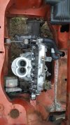
@MikeHynes I have heard about the alternator and axle intererence issue before, pretty sure both Steve H and Matt have said the same thing before on the forum, so I had already moved the alternator to another positon, seeing as I'm using a single carb there is room up top.

20201024_181841.jpg

@Steve Hoelscher no problem, any help anytime you can is always appreciated.

OK that is Looooow... the jack lift point looks almost scraping the ground! that is sort of the overall drop I'm thnking but with taller wheels / tyres so not '"quite" that low... if it's not a trade secret, was that ride height possible with the LCA's level? was thst from just moving the upper pivot point and tyre choice? or were there other pivot poit changes? I hadn't seen that picture before, first time I recall seeing you onlne was the very late 1990's and you had just gone 1X3 (I think or maybe 1X4) so havent seen many pictures of your earlier racing years before then.

I didn't know about the LH CV issue. I'm using a four / five speed hybrid transmission, so I have tripode inner joints and regular four speed outer CV's. I think the four speed type have more angular movement availabe as they came from a FWD car, so hoping this sin't a problem. There could be axle to case interference from the axle angle on the LHS, but I'll need to do a trial assembly.

smaller shifts that 55m front and 70mm rear of the ball joint pivot would be nice, but if can solve any trye clearance issues "looks like" a workable option

At the rear I could swap th OE ball pin for a spherical joint on top of the upright leg, but thats a smallish gain, as the shift is about 20mm down and 4 out, again I need to strip a rear ball joint apart to see what's possible, and then model to see if it's worthwhile

I'm more used to prepping rally cars, a lot of non tarmac stuff.. that was kind of my forte for a few years, so I'm still getting my head around all this wih such high spring rates ... I honestly understand the physics you're talking about... but I'm more used to having and actually wanting suspension travel and the car a little supple over bumps.

I'm also sticking with 14's as my brake package for both this car and the next street car build use 257mm discs all around. For "lemons spec" I really will need to stay on a 60 profile as well... the cost is a small consideraton, but the ease of availability of some decent 185/60/14 options seals the deal. I'm also having to make these 240 UTQG tyres last for 8 hours too. The long circuit we will be racing on the second day is known to be hard on brakes, which with a lot of negative camber is also really hard on the tyres.

I was kind of excited when I had a setup for the front that could roll 2.4 degrees and put the RC on the goundline right at the centreline of the inner tyres tread, and still had 0.30 negative on the outside tyre when I only started with just under 2 degrees negative to begin with. I'm sort of favouring a more "forgiving" setup too... let's be honest, we won't driving the lemon car 11/10ths like you drive your X19 DP car in a solo test, or generating anything like the G's...

I really need to stick with 120mm springs for now too, as I said I have a pair of 350lb rate, if I trim a coil / coil and a half from those the rate will increase and the ride height will be around where I want it for the "low" setup, theres 6.75 coils to start with. With the front I will have some springs made or find some that are at least 450/500lb/in in the free length I want.

the sway bar is from a lancia beta coupe, the rear bar from a FWD car, 17mm thick. The ends are too long but that's simle to trim off.

do you not think I can limit my body roll to 2.5 degrees roughly with that spring and bar combination? given the light body weight and (if I do the drop) low CG the car will have?

Quite a lot of the development / ideas from this build are carrying over to the next one (which will not be build budget limited) but that will be road registered, so a 3" drop is out of the question, the vehicle has to pass over a 100mm concrete step at the registration inspection, so that's as low as the lowest part of the underside can be, it can't scrape or touch as you drive over it and onto the inspection pit.

Lemons has no restrictions for ride height of course, so I was just trying to maximise any advantage and drop the CG as low as possible. I'm thnking the best route is setup the upper pivot / turret rework so it can handle both standard and lowered bj pivot pivots, that way I can have a fallback if the drop pivot setup ends up creating more engineering issues (which I may run out of time to overcome)

Its budget of time and funds I hadn't really allowed for... but I'll drop in to see my friendly machinist in the next couple of weeks with the spherical bearings (which are also not too cheap either) and see what he says. I've decided if I do all four ball joints I should use the same sized bearing / fastener sizing throughout, so it will be ABYT10 size

ABYT10 Spherical Bearing
Imperial:
0.6250" Bore x 1.3750" outside diameter x 0.567" Race width x 1.200" Ball width.
Metric:
15.875mm Bore x 34.925mm Outside Diameter x 14.40mm Race width x 30.48mm Ball width.

if I do the inner pivots front and rear, it will be ABTY7 size, but I might leave those rubber for now, again cost and time.

SteveC
 
Last edited:
"@MikeHynes I have heard about the alternator and axle intererence issue before, pretty sure both Steve H and Matt have said the same thing before on the forum, so I had already moved the alternator to another positon, seeing as I'm using a single carb there is room up top."
That should prevent bending your axle. But now...the weight of the alternator is up high - moving the center of gravity higher ;).
Just illustrates that building a racecar is all about tradeoffs! Sometimes you end up with a car that YOU have to learn to "drive through". It rewards an adaptable driver.
 
OK that is Looooow... the jack lift point looks almost scraping the ground! that is sort of the overall drop I'm thnking but with taller wheels / tyres so not '"quite" that low... if it's not a trade secret, was that ride height possible with the LCA's level? was thst from just moving the upper pivot point and tyre choice? or were there other pivot poit changes? I hadn't seen that picture before, first time I recall seeing you onlne was the very late 1990's and you had just gone 1X3 (I think or maybe 1X4) so havent seen many pictures of your earlier racing years before then.

I didn't know about the LH CV issue. I'm using a four / five speed hybrid transmission, so I have tripode inner joints and regular four speed outer CV's. I think the four speed type have more angular movement availabe as they came from a FWD car, so hoping this sin't a problem. There could be axle to case interference from the axle angle on the LHS, but I'll need to do a trial assembly.

smaller shifts that 55m front and 70mm rear of the ball joint pivot would be nice, but if can solve any trye clearance issues "looks like" a workable option

At the rear I could swap th OE ball pin for a spherical joint on top of the upright leg, but thats a smallish gain, as the shift is about 20mm down and 4 out, again I need to strip a rear ball joint apart to see what's possible, and then model to see if it's worthwhile

I'm more used to prepping rally cars, a lot of non tarmac stuff.. that was kind of my forte for a few years, so I'm still getting my head around all this wih such high spring rates ... I honestly understand the physics you're talking about... but I'm more used to having and actually wanting suspension travel and the car a little supple over bumps.

I'm also sticking with 14's as my brake package for both this car and the next street car build use 257mm discs all around. For "lemons spec" I really will need to stay on a 60 profile as well... the cost is a small consideraton, but the ease of availability of some decent 185/60/14 options seals the deal. I'm also having to make these 240 UTQG tyres last for 8 hours too. The long circuit we will be racing on the second day is known to be hard on brakes, which with a lot of negative camber is also really hard on the tyres.

I was kind of excited when I had a setup for the front that could roll 2.4 degrees and put the RC on the goundline right at the centreline of the inner tyres tread, and still had 0.30 negative on the outside tyre when I only started with just under 2 degrees negative to begin with. I'm sort of favouring a more "forgiving" setup too... let's be honest, we won't driving the lemon car 11/10ths like you drive your X19 DP car in a solo test, or generating anything like the G's...

I really need to stick with 120mm springs for now too, as I said I have a pair of 350lb rate, if I trim a coil / coil and a half from those the rate will increase and the ride height will be around where I want it for the "low" setup, theres 6.75 coils to start with. With the front I will have some springs made or find some that are at least 450/500lb/in in the free length I want.

the sway bar is from a lancia beta coupe, the rear bar from a FWD car, 17mm thick. The ends are too long but that's simle to trim off.

do you not think I can limit my body roll to 2.5 degrees roughly with that spring and bar combination? given the light body weight and (if I do the drop) low CG the car will have?

Quite a lot of the development / ideas from this build are carrying over to the next one (which will not be build budget limited) but that will be road registered, so a 3" drop is out of the question, the vehicle has to pass over a 100mm concrete step at the registration inspection, so that's as low as the lowest part of the underside can be, it can't scrape or touch as you drive over it and onto the inspection pit.

Lemons has no restrictions for ride height of course, so I was just trying to maximise any advantage and drop the CG as low as possible. I'm thnking the best route is setup the upper pivot / turret rework so it can handle both standard and lowered bj pivot pivots, that way I can have a fallback if the drop pivot setup ends up creating more engineering issues (which I may run out of time to overcome)

Its budget of time and funds I hadn't really allowed for... but I'll drop in to see my friendly machinist in the next couple of weeks with the spherical bearings (which are also not too cheap either) and see what he says. I've decided if I do all four ball joints I should use the same sized bearing / fastener sizing throughout, so it will be ABYT10 size

ABYT10 Spherical Bearing
Imperial:
0.6250" Bore x 1.3750" outside diameter x 0.567" Race width x 1.200" Ball width.
Metric:
15.875mm Bore x 34.925mm Outside Diameter x 14.40mm Race width x 30.48mm Ball width.

if I do the inner pivots front and rear, it will be ABTY7 size, but I might leave those rubber for now, again cost and time.

SteveC

I should note that the photo I posted above as a reference was of the car too low. That photo was taken at the 1994 SCCA Solo Nationals. The first season I ran the car (I built it over the winter of 1993 and '94), and before I knew much of anything about suspension. The car was built per what I had learned from others. It had a 1.5" (38mm) front swaybar and was as low as I could run it and still maintain useable suspension travel. I had built that car to replace my 1300 '74. I put everything I had learned from the '74 into it along with the inputs from other people I had "learned" from. It was terrible. I had expected a significant improvement in my performance over the previous year (in the '74) and finished in the exact same 6th position (in a field of 46 cars). I was frustrated to the point that on the tow home I vowed to educate myself on the subject and would no longer depend on the advise of others. The next year, with a completely revised setup, I narrowly missed winning my first championship. It is that car, from the event at which that photo was taken, that started me on a path that would result in a complete change of career.

So that photo, of MY car, is representative of "what not to do". Its too low and therefore rolls too much because the roll center is well below ground. It also had too much caster (resulting from being too low) and a host of other problems.

My MR2 is setup specifically to have 1 degree of body roll for every 1g of lateral load. So at 1.5 lateral g it rolls 1.5 degree. If you're running a 200+ TW tire on a 6" wide wheel, I would estimate about .9 to 1.0 max lateral g (sustained). Assuming you have everything else optimized. With a roll center between GL and +1" I would estimate wheel rate totals of roughly 500 lbs/in to have you in the range of 2.5 degrees. But there are a lot of variables obviously.

Now compare this photo. Same car, no swaybar, slightly higher, better geometry, way more lateral g and less body roll.

SouthFinish.JPG
 
Last edited:
This discussion has become very interesting in many ways. Got to wonder why so many get caught up into believing lowest is always best then ignoring or un-aware that lowest can be a very bad thing in many ways.

Bernice
 
This discussion has become very interesting in many ways. Got to wonder why so many get caught up into believing lowest is always best then ignoring or un-aware that lowest can be a very bad thing in many ways.

Bernice
I agree, for some I guess it's the old "if a little is good , then a little more must be better...." mentality.

Any input and ideas Bernice? I know you did a lot of setup work on your lemon, I recall a thread where you had it on wheel plates and scales... I'm not quite there yet, but those tools are almost affordable these days.

I've used a wheel lift weight gauge to set corner weights in the past, basically hooks onto the rim and by hand using a lever you lift the tyre just off the ground (a sheet of paper under the tyre lts you know when it's just lifted) and the weight reads on a small 2" hydraulic pressure gauge, sold for use on speedway cars like formula 500's and sprintcars...it means you go around and around to get it right, but eventually you do.

I know both yourself and Steve H are not fans of the "PBS method" of lowering an X19 chassis... what I find sort of funny is that I am kind of doing the exact opposite...

I'm leaving the inner lower pivot point alone (the one PBS suggest to move upwards) and instead I am moving the outer lower pivot point down

PBS suggests moving the upper pivot inwards (only) to gain camber, I'm moving the upper pivot up and in to change the roll centre and camber curves and adjusting camber at the hub/strut connection

PBS suggest moving the steering rack up. I'm leaving the rack where it is, but moving the outer tie rod pivot downwards (most likely - haven't got there yet)

PBS recommend the use of a very heavy front sway bar and a rear bar also, I may use a very light front bar, but definitely no rear bar.

@Steve Hoelscher I succumbed today and bought some threaded sleeves to make adjustable spring platforms to suit 2.25" diameter springs. At the front I could get away with reworking the strut tower quite easily to get the inward / upwards shift I want, but was stuck at about 45mm inwards change maximum with my standard 120mm diameter coils (wthout making it look really ugly.)

At the rear I just can't rework the tower inwards like I have at the front, but with a ball joint pivot drop it appears the ride height and roll centre / camber curve dont require as much "assistance" from moving this point inwards as the front does, but with 120mm coils I had very little space, so 2.25 inch coils it has to be to get the 20/30mm inwards and 30/40mm upwards move I need at the back for the top of the strut

The adjustable platforms will make it easier to choose a spring, it will make it (much) easier to set ride height, and it will also let me also corner weight the car, so it was something I wanted to do, but it's 4 x adjustable spring platform kits and 4 x coils on the shopping list now, and all lemons dollars spend. Hopefully the additional corner speed and ease of setup make it worthwhile. ... I'll have to rework my engine budget (probably be 1500cc now and not 1600? and drop the new 67.4mm stroke crank cost) and shift the extra needed money on the suspension budget.

I bought the same parts I've used on other cars, out of the UK as they are made for ford escort rally cars, 29GBP per kit so about $75aud per corner for the kits delivered/taxed, so thats $300 lemons spend
threaded sleeves struts.jpg

so I could go an all spring setup now 550F / 450R, and the 17mm front bar fitment can go on the backburner until I test the car and see how it feels.... or even a little firmer perhaps, as my RC's are more like 45mm rear and 55mm front, to be able to limit the total roll to the 2.5 degree target I'm thinking of. My only concern is the suitability of the dampers I have to control these sorts of spring rates. I only have road Koni adjustables up front, and basically standard Pedders oil inserts at the rear.

I was hoping to get 1G lateral sustained... I think that's about the practical limit of the tyres available so we are also close in our thinking on that point.

I also ordered the 4 x NMB ABYT10 spherical bearings today, not cheap little things at almost 40GBP each, so also about $75 each delivered/taxed and also out of the UK, but these are lemons free dollars as ball joints are free spend (it's a safety item - like wheel bearings)

So suspension stuff has to go on the backburner while I wait for parts to arrive, and then some machining gets done to fit the spherical bearings, so I can do a trial assembly, as really that's the only way to really tell if my idea is going to work as I want it to.

SteveC
 
Last edited:
This discussion has become very interesting in many ways. Got to wonder why so many get caught up into believing lowest is always best then ignoring or un-aware that lowest can be a very bad thing in many ways.

Bernice

I learned a number of lessons the 'hard way'. ie: following the advice of other, that probably didn't know much more than I did, or were simply wrong. The extreme low ride height and big front bar was copied from a competitor's car. He was a capable engineer but chassis/suspension weren't his primary field. His car was faster than mine but once I abandoned his methods, I was instantly faster. This was all in the very early days of the internet and well before there was such a wealth of knowledge available instantly.

Steve, good move on the coil-over sleeves. That makes things much easier. I would agree that 1g sustained is probably the upper limit for the wheel/tire package. That's actually quite good for the typical Lemons car.

Now that you have the coil-over sleeves it makes spring and setup changes much easier. I would recommend at least testing the all spring setup against the front bar setup. Of note: the all spring setup will require considerably more rebound dampening to control body motion. This due, not only to the higher rate springs, but also the rear chassis motion.
 
Steve, I agree with you on the PBS modifications. Technology and understanding of suspension geometry has become much better since it was written.

So, if you are going to move the outboard upwards, how are you going to control the excess camber this will cause, or is the total amount moved not enough to start causing issues with the contact patch of the tires. In other words, this: / \ vs. | | Sorry if I missed it in the previous threads, if this is the case, just let me know you already answered it and I need to re-read the thread more carefully. ;)

In terms of parts, in the US here, circle track racing is really popular in a lot of areas, and I have found their parts stores have lots of goodies for a good price. Here is just one example: https://www.speedmartinc.com/ This location use to be very close to where I lived and the costs for titanium fasteners were really good. In some cases, less than their steel counterparts.
 
Eric, there is considerable discussion about this earlier in the thread. Short version: Moving the top mount inboard improves the camber curve and raises the roll center, slightly. Camber can then be adjusted at the lower strut mount. This is the method I employed on my MR2.


Your comment about circle track parts vendor is accurate. In fact, when the SCCA Solo Nationals relocated to Lincoln Nebraska we were introduced to https://www.speedwaymotors.com They are there in Lincoln and instantly adopted the SCCA solo community. They hosted us for parties, sponsored the CAM class, produced promotional videos, etc.... They are great. I buy lots of stuff from them including much of the hardware used in the suspension on my MR2. Their pricing and service are excellent. And if you ever find yourself in Lincoln, their museum is well worth the time. I go back every year.
 
Technology and understanding of suspension geometry has become much better since it was written.....

So, if you are going to move the outboard upwards...

In terms of parts, in the US here, circle track racing is really popular in a lot of areas, and I have found their parts stores have lots of goodies for a good price.

Suspension theory and the physics involved in the weight transfer across the chassis hasn't changed, the bottom line is that P&B. S had their own idea about what would work best, and it can be shown that they were wrong. I'm not 100% sure but I don't think they ever actually won a championship with that car? We should be discussing the "Boig" method of "how to X19" perhaps as I know he did win at least one championship, but he never (as far as I know) put pen to paper and wrote about it.

I still have, and often refer to my favourite suspension book, "How to make your car handle" by Fred Puhn ... mines a first edition from 1975 and the information is still correct and that book is still in print.

Outboard pivot point (the ball joint) is moving down and out (not up) - both front and rear - which effectively reduces the negative camber at the wheel from tilting the strut over as far as I plan to, by pulling the bottom of the tyre back in by 10/12mm.

The "QA1" branded parts are not chrome moly, the NMB spherical bearings I bought are CrMo and rated to 15 plus Kilo newtons (about 45,000lbs)

I've used cheaper rod ends and spherial bearings in the past building rally cars, I found anything that's not CrMo just doesnt last, so I based my choice on materials selection not price point.

SteveC
 
Back
Top