Scuderia Ferric Oxide

Steve, I did the work on my X1/9 before there was reasonably priced suspension modeling software available. The work I did with the X1/9 was done the old fashioned way. I started with a spread sheet for wheel rate modeling then as I got deeper into the chassis itself to determine roll ratios.

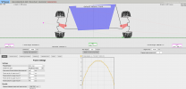
To figure out geometry, I used the illustrations in the work shop manual to make up a drawing that I could use to determine roll center heights and camber gain/loss. Actually making the drawings taught me a lot about what I was doing.

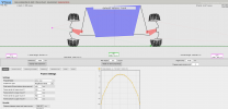
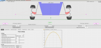
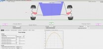
So I don't have models and I never got to the point of working out the relationships between strut inclination, camber curves and roll center heights. That I learned working on some of the production based GT cars I worked on. It was easy to migrate that knowledge over to the MR2 using Susprog3D (which by the way is an Australian product). While I lack specific data I can tell you that you can't move the struts too far inboard without modifying the strut towers. I would max out the available space and adjust camber at the upright/strut mount.

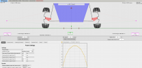
I don't suggest adding any additional caster, front or rear. The factory setting is 6 degrees which works very well. That's considerably more than is typical of production cars (3 to 4 degrees is pretty typical). There is an effect of caster called "trail", the distance between the steering axis intersection with the ground and the tire's contact patch, which gets exponentially longer as caster is increased. Increasing trail slows down the car's turn-in, or response to initial steering inputs. So there is a tradeoff. The rear has a similar, although greatly reduced, effect.

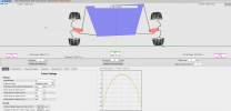
In the rear, use the same strategy for strut inclination and camber. You will find that the car will always need more rear grip so maximizing footprint is key to maximizing rear mechanical grip.

As for springs, have you tried sourcing used coil-over type springs? I would assume there is an online marketplace for used racing equipment and parts in Australia. There are lots of them here.
 
Altering the turret sheetmetal isnt an issue, it doesn't affect any class rules for any event I plan to enter the car in, all the other sheetmetal mods straight away shifted the build into the 2A sports car class, and the pointy end of the field are sports prototypes in the national class.

I have a pair of these turret tops, from an early 131, the bonus is that the top mounts I chose also suit the layout.
20210316_104705.jpg20210316_104713.jpg20210316_104759.jpg

so I'm thinking maybe 50mm inwards and 50mm upwards for the top pivot point, that lets me have the lower control arm level between the pivots and maintain 25 mm droop and 50mm compression travel at the strut shaft.

a bit like this, just a rough trial fit.
20210316_173619.jpg20210316_173653.jpg20210316_173707.jpg

I've done the drawing at 1/4 scale for camber curves for 128 sedan, 124 coupe, 131AR, and a mitsubishi starion in the past, but never got around to plotting everything when I was last involved with an X1/9 build... it's just very time consuming I guess and I was hoping to save the mental effort too.

but it's is as you say, keeping the angle between the virtual arm and the strut axis at under 90 degrees to keep the camber curve in the negative range and keep those outside wheels upright.

this is where my wheel and tyre will sit (more or less) at ride height
20210316_173539.jpg20210316_173554.jpg20210316_173634.jpg

SteveC
 
Last edited:
I was in two minds whether to add to your post again Steve, but I am happy to delete if not wanted.
Following the discussion on strut geometry I decided to have a go at an online calculator, VSusp.com. I measured up my track X as best I could and put the data in the program, I am a bit nonplussed, as moving the top of the struts in another 20mm seemed to have negligible benefit over adding the camber at the bottom of the strut with a camber bolt. Maybe I was expecting too much, or the program is not very good?? Any thoughts?
Screenshot_2021-03-17 VSusp default values.png

Approx settings on my track X currently, 0 body roll, roll centre above ground.


As before, but with 2.5 deg body roll, roll centre near rh tyre contact patch.


2.5 deg body roll, with top of struts moved in 20mm each, camber reset to original by adjusting strut at bottom. Roll centre at rh tyre contact patch as before.
Similar camber on outside wheel as before.
 

Attachments

  • Screenshot_2021-03-17 VSusp default values(1).png
    Screenshot_2021-03-17 VSusp default values(1).png
    124.9 KB · Views: 195
  • Screenshot_2021-03-17 VSusp default values(3).png
    Screenshot_2021-03-17 VSusp default values(3).png
    123.4 KB · Views: 198
Last edited:
@GregS that's a pretty cool suspension modelling programme, but to make sense of the data you've shared you'd also need to share the other values you've input for distance between / length of components...

but I can certainly see myself spending a little time having a play with this, easier than drawing it all out.

SteveC
 
Greg, I am unfamiliar with the application you are using here. In review it appears that there is something wrong with how the application renders the virtual strut geometry for the difference in top mount location. It doesn't seem to change the angle of the virtual strut and thus the camber reference is inaccurate.

Also, perhaps you have misunderstood the purpose behind moving the top mounts inboard. Yes, it does raise the roll center but the effect isn't significant. The purpose is to shift the transition point of the camber gain/loss curve further up the bump travel. The effect is a slight improvement in the rate of camber loss as the car rolls and compresses the outside suspension.

Note, in the top illustration, the acute angle between the control arm and the virtual strut (the line between the top strut mount and the ball joint). Then note the position of your roll center. If you were to lower the car further, the control arms would no longer be parallel to the ground, and the acute angle between the control arm and the strut would become a right angle (90 degrees). So the static ride height would be right at the camber curve's transition point to positive. Moving the strut top inboard would make that angle less than 90 degrees and improve the camber curve at static ride height.

One final note: its hard to tell from the screen capture but is the roll center at static ride height 66mm? That's somewhat higher than ideal.
 
Have had another go at the calc and added more info.
The lower control arm length used is 275mm, measured from the ball joint to a line between the inner control arm pivot and the front mount of the radius arm. Tyres 185/60 13 on 6" rims, 19mm offset and 9mm hub spacers.
Top of struts moved in 20mm (470 to 450), camber adjusted to -3 deg, 0 roll, RC moved to 68mm above ground.

Yes, the static roll centre height was 66mm. My second go at the calc I have made the adjustments by moving the top strut mounts as before, but adjusted the strut angle to get the desired static camber.
The RC is still around 60mm. Camber at 2.5 deg roll is only improved by 0.2 deg. A lot of effort for not much improvement.

Thinking about it now, I think there is something I am doing wrong to reset the camber after moving the strut tops inwards. I think the program doesn't allow for adjusting with camber bolts. I changed the strut angle to get -3 deg, only other option I can see is to change the hub to strut bottom horizontal distance that I did first time around.
I can see if I wanted to lower the car significantly more it would be an advantage.
Thinking of changing front springs to 550 lb, and 360 lb on the rear.
 

Attachments

  • Screenshot_2021-03-18 VSusp x19.png
    Screenshot_2021-03-18 VSusp x19.png
    124.2 KB · Views: 137
  • Screenshot_2021-03-18 VSusp x19(1).png
    Screenshot_2021-03-18 VSusp x19(1).png
    126.1 KB · Views: 128
  • Screenshot_2021-03-18 VSusp x19(2).png
    Screenshot_2021-03-18 VSusp x19(2).png
    118.1 KB · Views: 129
  • Screenshot_2021-03-18 VSusp x19(3).png
    Screenshot_2021-03-18 VSusp x19(3).png
    122.8 KB · Views: 136
Last edited:
I drew one side of the suspension layout on the floor with engineers chalk at 1:1 scale this afternoon, I came up with a few different numbers than your inputs.
20210318_154831.jpg

the vertical line at the wheel side isn't the wheel C/L, it's the face of the wheel hub / flange. on to this add disc flange depth and any spacers. to determine track width

the LCA inner point on the chassis, the points are 645mm apart at their centres according to the chassis diagram, so 322.5mm for "frame centre to lower mount X"

the upper pivot point for the strut is listed as 481.5mm to the centreline, according to section AA of the chassis plans, so that's "frame centre to upper mount X

the upper pivot point is 418mm above the wheel centreline, which is 51mm above the LCA pivot point, which 70mm above the floor line, this makes the upper pivot point 539mm above the floor line.

The LCA inner point is shown as being 51mm below the wheel centreline, with standard 145/80 13 tyres thats a 281mm radius, say 280mm to alllow for the tyre flattening at the base, which puts the LCA inner pivot at 70mm above the floor line, which is 159mm above the ground line, so the inner pivot is 229mm above ground line at standard ride height

I measure the length of the LCA, when viewed from the front, at 235mm.

I have moved the upper pivot point 40mm inwards each side, and 25mm upwards. To keep the LCA level the chassis can only come down 14mm, so the LCA inner pivot is then 215mm above ground line.

If you work out the camber loss with standard positioned top pivot points, and modified ones, with the 185/60/14 tyres /14 inch Lancia 34mm offset rims/ disc flange and disc spacer is 16mm, plus up to 32mm of spacers (2 x 16mm alloy) I'm thinking of using up front...

40mm inward /25mm upward shift results in a RC 52mm above ground level, and 1.61 degrees of camber loss at 2 degrees of body roll... and 2.52 degrees of loss at 3 degrees of body roll

with the standard upper pivot position it results in 1.9 degrees camber loss for 2 degrees roll and 2.9 degrees loss at 3 degrees roll.

If I have my front camber set at 2.75 degrees negative, with modified upper pivot points at 3 degrees of roll I still have 0.23 of a degree negative camber and loads of grip as I have maximum tyre footprint... with the stock position I'm at positive 0.15 camber and significant mechanical grip has been lost at the same amount of roll.

fiat x19 modified

the interesting thing is, as the tyre aspect drops and the ride height / LCA arm is reset to level, the roll centre lifts, and the camber loss with body roll reduces even more, so with a 185/50/14 tyre the RC is 47mm, so the roll centre only drops by 5mm even though the chassis now sits 18mm lower , LCA pivot is 197mm above ground line and at 3 degrees of roll there is still 0.27 of a degree negative camber on the outside wheel. So a change in tyre aspect ratio from 60 to 50, lets me drop the chassis a further 18mm from the height with 60 profile tyres, so a full 32 mm lower than standard (even with 14 inch wheels)

fiat x19 modified 50 profile

with a 185/40/14 tyre (which would be a race slick), the ride height comes down again with the LCA pivot at 179mm above GL, RC is 46mm above GL, and 2.49 degrees of camber loss at 3 degrees roll, so with a ride height and tyre change to race slicks, I can drop the chassis a further 18mm again and still maintain the same basic geometry.

so after trying many different combinations, I think what I'm going to aim for is this.
40mm inward shift of the upper pivot point (441mm to CL), 32 mm upward shift of same, LCA inner pivot point is 198mm from GL at ride height, RC at 47mm

fiat x19 modified 40/32 50 profile

@Steve Hoelscher what do you think? do the numbers I've input look about right to you?


SteveC
 
Last edited:
fiat x19 modified 40/32 50 profile

@Steve Hoelscher what do you think? do the numbers I've input look about right to you?


SteveC

Yes, that looks similar to what I saw doing the same exercise on my MR2.

I have tried a few of the online suspension analysis tools and often found them to be problematic. Either the results weren't somewhat similar to what I could see with my own practiced eye or they didn't align with what I had produced with susprog3d.

As a follow on note; I have found, via testing, that my X1/9, and now my MR2, both tend to work best with a rear roll center height in the range of 10 to 20mm above ground in the rear and the front slightly above that. I start in that range and tune from there via testing. The modern Hoosier A7 tires seem to prefer the roll center very close to ground level.
 
I drew one side of the suspension layout on the floor with engineers chalk at 1:1 scale this afternoon, I came up with a few different numbers than your inputs.
View attachment 44961
the vertical line at the wheel side isn't the wheel C/L, it's the face of the wheel hub / flange. on to this add disc flange depth and any spacers. to determine track width

the LCA inner point on the chassis, the points are 645mm apart at their centres according to the chassis diagram, so 322.5mm for "frame centre to lower mount X"

the upper pivot point for the strut is listed as 481.5mm to the centreline, according to section AA of the chassis plans, so that's "frame centre to upper mount X

the upper pivot point is 418mm above the wheel centreline, which is 51mm above the LCA pivot point, which 70mm above the floor line, this makes the upper pivot point 539mm above the floor line.

The LCA inner point is shown as being 51mm below the wheel centreline, with standard 145/80 13 tyres thats a 281mm radius, say 280mm to alllow for the tyre flattening at the base, which puts the LCA inner pivot at 70mm above the floor line, which is 159mm above the ground line, so the inner pivot is 229mm above ground line at standard ride height

I measure the length of the LCA, when viewed from the front, at 235mm.

I have moved the upper pivot point 40mm inwards each side, and 25mm upwards. To keep the LCA level the chassis can only come down 14mm, so the LCA inner pivot is then 215mm above ground line.

If you work out the camber loss with standard positioned top pivot points, and modified ones, with the 185/60/14 tyres /14 inch Lancia 34mm offset rims/ disc flange and disc spacer is 16mm, plus up to 32mm of spacers (2 x 16mm alloy) I'm thinking of using up front...

40mm inward /25mm upward shift results in a RC 52mm above ground level, and 1.61 degrees of camber loss at 2 degrees of body roll... and 2.52 degrees of loss at 3 degrees of body roll

with the standard upper pivot position it results in 1.9 degrees camber loss for 2 degrees roll and 2.9 degrees loss at 3 degrees roll.

If I have my front camber set at 2.75 degrees negative, with modified upper pivot points at 3 degrees of roll I still have 0.23 of a degree negative camber and loads of grip as I have maximum tyre footprint... with the stock position I'm at positive 0.15 camber and significant mechanical grip has been lost at the same amount of roll.

fiat x19 modified

the interesting thing is, as the tyre aspect drops and the ride height / LCA arm is reset to level, the roll centre lifts, and the camber loss with body roll reduces even more, so with a 185/50/14 tyre the RC is 47mm, so the roll centre only drops by 5mm even though the chassis now sits 18mm lower , LCA pivot is 197mm above ground line and at 3 degrees of roll there is still 0.27 of a degree negative camber on the outside wheel. So a change in tyre aspect ratio from 60 to 50, lets me drop the chassis a further 18mm from the height with 60 profile tyres, so a full 32 mm lower than standard (even with 14 inch wheels)

fiat x19 modified 50 profile

with a 185/40/14 tyre (which would be a race slick), the ride height comes down again with the LCA pivot at 179mm above GL, RC is 46mm above GL, and 2.49 degrees of camber loss at 3 degrees roll, so with a ride height and tyre change to race slicks, I can drop the chassis a further 18mm again and still maintain the same basic geometry.

so after trying many different combinations, I think what I'm going to aim for is this.
40mm inward shift of the upper pivot point (441mm to CL), 32 mm upward shift of same, LCA inner pivot point is 198mm from GL at ride height, RC at 47mm

fiat x19 modified 40/32 50 profile

@Steve Hoelscher what do you think? do the numbers I've input look about right to you?


SteveC
Steve, I can see why some of your suspension points are different to mine, others not so much. Strut tops for instance, you used factory figures for the top of the strut tower, I used my track X actual current strut pivot points with their extra neg camber. The virtual LCA I definitely get 275mm not 235mm, and distance apart on my car is 630mm not 645.
I will be following your project with interest, good luck.

factory diagram lists the LCA pickup with two figures, as the hole is angled to the chassis centreline. My number is the middle of the bracket to centreline, your measurement will be to the centre of the bolt head , which isn't the true pivot point.

I'll need to defer to Steve H on this, but again I think you've miscalculated the "straight on" view length of the LCA. You have measured to a point in space between the LCA inner and the Brake Reaction Rod pivot, I think that's where you've gone wrong, but I'll defer the full answer to Steve H as I said as I'm sure he will clarify the point.

I have always believed the front LCA length in this case was veiwed from straight ahead, and the pivot axis is the LCA inner bolt.

Strut tops, not so much the width from centreline, but the height from goundline/floor line, you have that as 495, and stock it's 539mm

SteveC
ok, I see I didn't allow for the angle of the LCA bracket. But that still doesn't account for the 40mm length discrepancy, viewed front-on the front locating point is almost inline with the rear, maybe 10mm or so closer to the centreline.
The 495mm on my diag is to the bottom of the sills, 663 from strut top pivot to the ground, yours I believe is 710, the difference mostly from my lower profile tyres, lowered suspension, and estimate of the location of the top pivot point in the rubber mount.
Probably none of these will make a huge difference to the calculations. Cheers, Greg.
 
Probably none of these will make a huge difference to the calculations. Cheers, Greg.

well the LCA length and pivot point are about the most crucial measurement...

if I sustitute the figures for LCA position and your altered (470 to CL) top pivot point, with your wheels and tyres, I get this.

inputting these numbers gives a point in space for the upper pivot point at 539mm + 122mm for this point by calculation by my numbers, so 661mm and you say 663mm by direct measurement, that's well under 1% variance using the standard 539mm as the frame to strut pivot figure

your telling me that your LCA inner point is 192mm from ground level with the figures you've given, with that wheel and tyre combination your LCA is already angling upwards at this ride height.

fiat x19 GregS

SteveC
 
Last edited:
Steve, that looks pretty nasty, but it's not really what I have. If I use your 322.5mm Frame Centre to lower mount x, and all the other data as I measured, including my 275mm LCA length and knuckle settings, the LCA is horizontal, and it looks like this readout. The LCA is actually horizontal in real life, sitting on worn tyres at 22 psi.
 
The LCA is actually horizontal in real life, sitting on worn tyres at 22 psi.

When people say that to me it usually means they are measuring incorrectly, I see it all the time in 124's.

If your're telling me the lower contriol arm "looks" level, then I know it isnt level between the PIVOT POINTS, which is what we are interested in.

This explains some of the different dimensions you have for the balljoint offset from wheel centreline... the pivot points are marked in this picture
20210319_205413_LI.jpg


the pivot points are the X's, so if the control arm looks level the pivot point is approx 19mm higher than the inner pivot, I think you're eyeing the dimensions at where the dotted line is crossing the ball jont pin, where it enters the upright, it's a very common mistake.

I understand this suspension programme has limitations, as it's modelling something 3D in 2 dimensions, same goes with me drawing it on the workshop floor at 1:1, I can't accout for the caster of the strut in my dimensions, and I've made the camber zero measured at the wheel flange to make it easy for myself. usinf the factory track of 1335 and working backwards, same with the suspension programme, I began by inputting all the standard dimensions first, and then altering tyres/wheel size, upper points.
20210319_205030.jpg20210319_205059.jpg20210319_205128.jpg

@Steve Hoelscher

is the dimensional length for the LCA based on the "looking straight from the front" view distance from LCA inner pivot to the ball joint pivot centre?

Or would you draw an imaginary line between the LCA inner pivot and the front brake reaction rod pivot, bisect this in space, and at this point in space measure back to the ball joint pivot?

I was going to ask you a similar question sooner or later about the rear suspension, as to model that I'm not 100% sure where to draw the line between the pivot(s) and ball joint ... I kind of feel that it all measures of the rear leg of the lower control arm, as that's where the toe link is so it seems to me that's the pivoting axis, but I just want to be 100% sure.

SteveC
 
Last edited:
When people say that to me it usually means they are measuring incorrectly, I see it all the time in 124's.

If your're telling me the lower contriol arm "looks" level, then I know it isnt level between the PIVOT POINTS, which is what we are interested in.

This explains some of the different dimensions you have for the balljoint offset from wheel centreline... the pivot points are marked in this picture
View attachment 45030

the pivot points are the X's, so if the control arm looks level the pivot point is approx 19mm higher than the inner pivot, I think you're eyeing the dimensions at where the dotted line is crossing the ball jont pin, where it enters the upright, it's a very common mistake.

I understand this suspension programme has limitations, as it's modelling something 3D in 2 dimensions, same goes with me drawing it on the workshop floor at 1:1, I can't accout for the caster of the strut in my dimensions, and I've made the camber zero measured at the wheel flange to make it easy for myself. usinf the factory track of 1335 and working backwards, same with the suspension programme, I began by inputting all the standard dimensions first, and then altering tyres/wheel size, upper points.
View attachment 45031View attachment 45032View attachment 45033

@Steve Hoelscher

is the dimensional length for the LCA based on the "looking straight from the front" view distance from LCA inner pivot to the ball joint pivot centre?

Or would you draw an imaginary line between the LCA inner pivot and the front brake reaction rod pivot, bisect this in space, and at this point in space measure back to the ball joint pivot?

I was going to ask you a similar question sooner or later about the rear suspension, as to model that I'm not 100% sure where to draw the line between the pivot(s) and ball joint ... I kind of feel that it all measures of the rear leg of the lower control arm, as that's where the toe link is so it seems to me that's the pivoting axis, but I just want to be 100% sure.

SteveC

This is exactly why I use the term "virtual control arm" and "virtual strut". People usually assume the control arm angle is the actual angle. Same for the strut. They are not.

This is also why the most critical part of analysis is getting accurate data.

As for the calculator, it appeared to me that when the top mount was moved inboard, the angle of the strut didn't change. I wish I had more time to delve into this but I have three major projects on my plate right now. One just launching and two wrapping up in the next week.
 
When people say that to me it usually means they are measuring incorrectly, I see it all the time in 124's.

If your're telling me the lower contriol arm "looks" level, then I know it isnt level between the PIVOT POINTS, which is what we are interested in.

This explains some of the different dimensions you have for the balljoint offset from wheel centreline... the pivot points are marked in this picture
View attachment 45030

the pivot points are the X's, so if the control arm looks level the pivot point is approx 19mm higher than the inner pivot, I think you're eyeing the dimensions at where the dotted line is crossing the ball jont pin, where it enters the upright, it's a very common mistake.

I understand this suspension programme has limitations, as it's modelling something 3D in 2 dimensions, same goes with me drawing it on the workshop floor at 1:1, I can't accout for the caster of the strut in my dimensions, and I've made the camber zero measured at the wheel flange to make it easy for myself. usinf the factory track of 1335 and working backwards, same with the suspension programme, I began by inputting all the standard dimensions first, and then altering tyres/wheel size, upper points.
View attachment 45031View attachment 45032View attachment 45033

@Steve Hoelscher

is the dimensional length for the LCA based on the "looking straight from the front" view distance from LCA inner pivot to the ball joint pivot centre?

Or would you draw an imaginary line between the LCA inner pivot and the front brake reaction rod pivot, bisect this in space, and at this point in space measure back to the ball joint pivot?

I was going to ask you a similar question sooner or later about the rear suspension, as to model that I'm not 100% sure where to draw the line between the pivot(s) and ball joint ... I kind of feel that it all measures of the rear leg of the lower control arm, as that's where the toe link is so it seems to me that's the pivoting axis, but I just want to be 100% sure.

SteveC
Steve, my virtual control arm is ball joint to pivot bolt, although it is just an estimate to where the centre of the ball is.
BUT, I did have the hub to ball joint height incorrect, I had left it at the default 80mm, my estimate is it is approx 70mm (you have used 65), I find it's hard to tell exactly where the ball centre is.
Using 70mm it has lowered the RC to +33mm, but at 2 deg roll it goes to -63mm and way outside the track width. Not so good. I will have to have another look at it.
 
yes the 65mm measurement is also an estimate, but I would tend to under estimate this dimension by a mm or two , so that when it comes to lowering the car there is margin for error, and the virtual arm is going to be level or angled down to the wheel by that mm or two, over estimating it by a couple of mm would automatically result in a "bad" camber curve in real life.

As you've just shown, 10mm incorrect and the LCA goes from level to nearly 2 degrees (1.875), that's with the baljoint offset at 70mm (which is an over estimation, it's actually about 67, maybe 67.5mm) input 67.5mm as this value and the angle grows again to 2.5 degrees and the RC drops to 24mm

It's actually more as your virtual LCA is also too long - for a start you added 7.5mm to the width to CL for the LCA inner pivot to make that 322.5 as it should be, but you kept your LCA length at 275mm, so you just pushed your track out by 15mm if you don't at least correct the LCA length back to 267.5mm.

make that change to the dimensions (LCA at 267.5mm as well as the ball joint 2.5mm) and your arms angle up at 2..786 degrees, and the RC is just 15mm above ground line, you need to raise the ride height by 13.5mm to get the LCA level, and then the RC is back at 57mm above ground line.

So I don't doubt that your front LCA's "look" level, but it's quite obvious that they are not level between the pivots.

Ideally I'd be plotting all the points on a flat level floor, dropping the measurements down to floor line with a plumb bob and then taking the car away and "connecting the dots" on the floor to get the straight line measurements, but I dont have an X19 on four wheels and a flat level surface handy, so I'm using the factory dimensions and trying to work backwards.

Even doing it with a plumb bob requires several measurements for each point, the LCA inner for example you need to plot the two hole centres, and bisect the line they make to find the pivot centre... same with the ball joint, plumb bob down each side (f & r) of the ball and then bisect to find it's centre.

You would then need to draw lines from these points that are parallel to the vehicle centreline, where these two lines for LCA inner and BJ pivot cross the wheel centreline, would be the correct LCA virtual length, so my 235mm measurment may be 5mm too short as I'm not allowing for the caster forward offset, so my measurement on the floor will be short.... but if your measuring to a point that bisects the forward and rear pivot points, you are measuring back to the ball joint pivot from well ahead of wheel centreline, and hence quite a bit too long

virtual LCA length.jpg


what we want to determine is length AB, you're measuring (from your description, please correct me if I'm wrong) the distance AC, which is the Hypotenuse of the (pretty close to) right angle triangle ABC

SteveC
 
Last edited:
Hi Steve, I guess I am just wasting my time taking approximate measurements, I wanted to get a ballpark idea what my suspension was doing to see if it's worth making mods. I will have to make time and use a plumb bob like you suggested. Out of interest my LCA measurement was for A-B in your diagram, but I would say it is probably more like 265mm, still approx. And my virtual LCAs are almost exactly level on the car, between pivots, so I am guessing it is a buildup of small errors that is showing them at an angle. I did try the calculator again with the inner frame point 10mm higher to make them level, and the 265 length, and the geometry looked a lot better. But I won't do any more with it untill I can measure everything properly. Cheers
 
This afternoon I re drew the layout on the floor, this time I sharpened my chalk as I was going so I got much finer lines (I already knew what I was doing too). I will happily concede that my initial virtual LCA meausrement was a little short, re drawing it I get closer to 240mm (239.5) and if I allow for the caster offset, and do a little trigonometry, I come up with a number of 245mm.

now this fits very nicely with all my other measurements, becuase for the first time I'm seeing the actual track of the car showing correctly, before it was narrow by about 20/25mm depending on settings... I was wrong when I figured this out as I was only allowing 20mm spacer not 32mm of spacer (my two options at the moment are 20mm and 16mm thick)

(See my next post after spending many hours measuring the car)

Now the next issue in your simulation, is the height of the strut pivot to ground level your using. I think the whole floor level thing is a bit confusing, so I've made that zero in all simulations, and simply made the LCA inner pivot point height the floor level as well. It makes no difference for our application anyway, perhaps if we were building formula fords with chassis 30mm from the ground it would, but it makes the whole thing more confusing, so we will drop "floor line" from our vocabulary for this discussion.

we know the LCA pivot is 51mm (well 50.5mm to be exact) below wheel centreline at standard wheel size, we also know that standard strut top pivot point is 418mm above wheel centreline, that makes the vertical distance from the LCA inner pivot to the strut upper pivot 469mm at standard position. That doesn't change no matter what tyre size or spring length we use. The only way this point moves upwards from 469mm is if we move it.

OK so if we input 469 as "floor" to upper pivot length, 322.5 as CL to lower pivot, 72.5mm as the ball joint offset 265.5mm for virtual LCA this is with Gregs 13 x 6 / 9mm offset wheels, 185/60/13 tyres and 10mm spacer, we get.

fiat x19 GregS 10/ std 60 profile 13

If I use all the same numbers, and model the two most likely variations I'll probably set up on (60 series tyres and 50 series tyres) with my turret top changes with my 14 inch 34mm offset wheels and 185 section tyres

this is what I get

fiat x19 SteveC 40/30 60 profile 14 (this is top pivot moved inwards 40mm each side, and 30mm upwards from original position)

fiat x19 SteveC 50/30 50 profile 14 (this is top pivot moved inwards 50mm each side, and 30mm upwards from original position)

again with these numbers - now - it shows the track correctly with my 15.5mm disc width and a 20mm spacer fitted and the major pickup points (albeit in only 2D) are modelled on known and / or published data.

anyone wishing to give the modelling a go,

the standard width between the upper pivots to centreline is 481mm
the standard distance from lower inner pivot to centreline is 322.5mm
the distance from lower pivot (floor) to upper pivot is 469mm
the distance for the virtual LCA is 265.5mm
the distance from the strut cenreline to the WHEEL FLANGE line is 130mm, to this add disc mount thickness and any spacer thickness, standard disc is 11.5mm, standard spacer is 5mm, so the standard measurement from strut centreline to wheel mount face is 141.5mm
the standard pressed steel 4.5 inch series 1 wheels have a 35mm offset
the distance from wheel centreline to ball joint pivot is 72.5mm
and the ride height measurement is the disatnce from ground line up to the centreline of the inner lower pivot bolt head on your car

Input your wheel / tyre size and wheel offset and see what you have..

SteveC
 
Last edited:
Virtual lower pivot points have been a thing for a while. They give the engineers more freedom in reducing scrub radius, etc. as you can project a virtual joint to a location that would be inaccessible to package an actual joint. The goal being to have the steering axis more in line with the "virtual" lower ball joint. Particularly important on drive axles. That's why you see cars with two "actual" lower ball joints now. Adds cost, of course.

Cool video of it in action:

1616245332385.png


Citroen solved the problem by using inboard brakes to allow them to physically put the joint where they wanted it.

1616246453890.png
 
Back
Top