
You are using an out of date browser. It may not display this or other websites correctly.
You should upgrade or use an alternative browser.
You should upgrade or use an alternative browser.
Selling the X & Bought an 75 Datsun 280Z
- Thread starter lookforjoe
- Start date
kmead
Old enough to know better
Indeed. Always some learning nuggets in the posts.I hope you know how much I appreciate your time and dedication to this thread. Quite a bit of fun watching it, and also even though it has been probably 40 years since I sat in one and drove it, I can still smell it (in a good way!)
lookforjoe
True Classic
Now that I've driven the car for days in row, commute to work, local & mixed highway driving - I have found that there is what I would call a heat soak issue. When restarting a hot / normal op temp engine after a few minutes of sitting (after getting coffee, for example), it will crank REALLY slowly for a couple of revolutions, then pickup to normal cranking speed.
Having redone the wiring with suitable gauge cables, added the starter relay to offload the switch, and changed the breaker on the starter leg of the battery cable to a higher amperage, I can't see what else it could be besides the starter itself. I did replace the one that was in there with a reman (RockAuto - Remy 16209) in June of this year. I'll have to see if I can measure the draw from the starter, duplicating the symptom when I have equipment available to test it is the trick.
EDIT - I just swapped out the old starter for the reman that was in there after work. Cranks really nicely now, even hot. RockAuto will refund me for the bad starter, minus shipping. I've ordered a new-production gear-reduction version intended for the later L6 280ZX.
Last edited:
lookforjoe
True Classic
Changed the gas filler protector flap & cap seal

Licence plate lamp painted, BFM0360 Dark Shadow Gray. Waiting for the 'chrome' paint to fully cure before I assemble the side panels

Licence plate lamp painted, BFM0360 Dark Shadow Gray. Waiting for the 'chrome' paint to fully cure before I assemble the side panels
lookforjoe
True Classic
I was nervous about doing this today - given the posts talking about difficulty of removing the plugs.
I used a 17mm crow foot w/the 1/2 drive ratchet on the trans, 17mm wrench with another wrench hooked over it for leverage. Both came out without any real drama.


diff drain - some metal particles


I used my trusty transaxle fill tube- it's a crankcase breather hose from a 90's Volvo

Diff took about 1.2 quarts (GL-5) before it started coming out the fill plug


trans

Trans took 2 quarts (Gl-4) - just started dripping out the fill plug with that

only got one quart out of the trans

Found that the reverse light switch is dead - easy to test since I had it in the air

While I had the car in the air, and the temps are back in the 70º range, I got the side decals on.


lookforjoe
True Classic
Test fitted the panels - still waiting for the gaskets before I actually install them. They (the chrome areas) look pretty rough up close. Still better than they were.


lookforjoe
True Classic
I put in my old Hella H4's (from the X1/9) with the LED bulbs Steve (on ClassicZ) recommended - Auxito 6500K white. One of the Hella housings has minor water damage, so I ordered the Kioto H4 housings while they are still available from Toyota, at such a good price.
housings came out smoothly, no snapped or stripped hardware. I didn't order new gaskets, so I cleaned & lubricated them for reinstall

Comparison of sealed (low) beam to LED

Adjusted the hatch - much better now, no more slamming required. I did have to make it a touch tighter than I wanted, to make sure the horizontal seal was snug against the hatch - don't want any fumes sucking in. Paper pull test to check


lookforjoe
True Classic
I had to redo the chrome - the center recess on them where the foil was peeling bothered me too much. I filled the recess yesterday's then sanded, masked & repainted the chrome today. It's still got imperfections, but better overall


Now that I have the H4's installed, I decided it was finally time to add the headlight covers I got from Motorsport Auto back in the Spring
Probably going to paint the brackets, doubt I can stand looking at those


Now that I have the H4's installed, I decided it was finally time to add the headlight covers I got from Motorsport Auto back in the Spring
Probably going to paint the brackets, doubt I can stand looking at those


dllubin
Don
What are you using to paint the chrome? I've got a couple of my mag center caps that have lost a good bit of their chrome and I was wondering if there was a good solution that was not too difficult to deal with.I had to redo the chrome - the center recess on them where the foil was peeling bothered me too much. I filled the recess yesterday's then sanded, masked & repainted the chrome today. It's still got imperfections, but better overall
lookforjoe
True Classic
Rustoleum Metallic (Chrome) FinishWhat are you using to paint the chrome? I've got a couple of my mag center caps that have lost a good bit of their chrome and I was wondering if there was a good solution that was not too difficult to deal with.
Another splurge. New reproduction factory mirror
Fitted the luggage straps. I think I have them backwards
Refitted the HEI module & Volvo coil. With the good starter, the system worked as expected, cranked normally & started right up... but... the tach doesn't work. Switched back to the stock system.
Found an older post from another Z member who said he had to put a higher value resistor to get the tach to work. Stock value for the inline tach resistor is 2.2K, I found a post where they added a 5- 5.5K value of resistor for the tach to work.
Last edited:
lookforjoe
True Classic
Covers with lights on


 l
l
Kioto housings arrived, so I have to swap out the Hellas soon.

Also installed the new reverse light switch. Apparently they don't last, so maybe I'll use the switch output to trigger a relay instead of directly powering the reverse bulbs.


 l
lKioto housings arrived, so I have to swap out the Hellas soon.

Also installed the new reverse light switch. Apparently they don't last, so maybe I'll use the switch output to trigger a relay instead of directly powering the reverse bulbs.
Last edited:
lookforjoe
True Classic
OK - so finally had the time & break in the weather to swap out the coil & module.
I did first just plug in the HEI module with the stock 6V coil & ballast, and as expected the tach functioned normally with the stock 2.2K ohm resistor.
I swapped to the 12V coil and ballast bridge, and tried the 5K ohm resistor bridge. Tach operated briefly, then dropped. I then added a 1K resistor in series with the 5K, and that was better, but tach was still erratic & dropped out after a bit. Added another 9.8K (though I was adding 500ohm) and with that, the tach smoothed out, held normal idle rpm & revved freely in time with the engine. So, for me, 1580ohms is the value required.
I drove the car to work this evening for my parent-teacher conferences, and I have noticed that there is a noticeable 'jerkiness' on throttle tip-in that is not present with the stock ignition setup. Not sure why that would be, I'll have to see if it persists. I also have not swapped out the generic Standard Motor Part module for the geniune GM module, so it is possible that is the culprit I suppose.

made final version with a 14.8K + 1K resistors in series, tie wrap under shrink wrap to act as a spine


Also fixed the break in the louvre fin that was causing an annoying rattle over bumps

made a U channel from SS plate, riveted on either side of the fracture

I did first just plug in the HEI module with the stock 6V coil & ballast, and as expected the tach functioned normally with the stock 2.2K ohm resistor.
I swapped to the 12V coil and ballast bridge, and tried the 5K ohm resistor bridge. Tach operated briefly, then dropped. I then added a 1K resistor in series with the 5K, and that was better, but tach was still erratic & dropped out after a bit. Added another 9.8K (though I was adding 500ohm) and with that, the tach smoothed out, held normal idle rpm & revved freely in time with the engine. So, for me, 1580ohms is the value required.
I drove the car to work this evening for my parent-teacher conferences, and I have noticed that there is a noticeable 'jerkiness' on throttle tip-in that is not present with the stock ignition setup. Not sure why that would be, I'll have to see if it persists. I also have not swapped out the generic Standard Motor Part module for the geniune GM module, so it is possible that is the culprit I suppose.

made final version with a 14.8K + 1K resistors in series, tie wrap under shrink wrap to act as a spine


Also fixed the break in the louvre fin that was causing an annoying rattle over bumps
made a U channel from SS plate, riveted on either side of the fracture
Last edited:
lookforjoe
True Classic
OK - so on the drive home from work this afternoon I drove it pretty hard - higher rpm shifts, kept it in 3rd for longer, and drove at higher speed than normal. The engine does feel more 'crisp' & responsive with the HEI module - BUT - it started breaking up much worse on the last leg of my highway run, had to back off the throttle, and it still kept clipping/dropping out. I'm assuming it's the bootleg brand module, so I took the time to swap it out for the GM one. I found that to access that area of the relay panel, the glovebox had to come out, so I decided to relocate the module where I could access it more readily. If the problem persists, I'll just switch back to the stock ignition system.

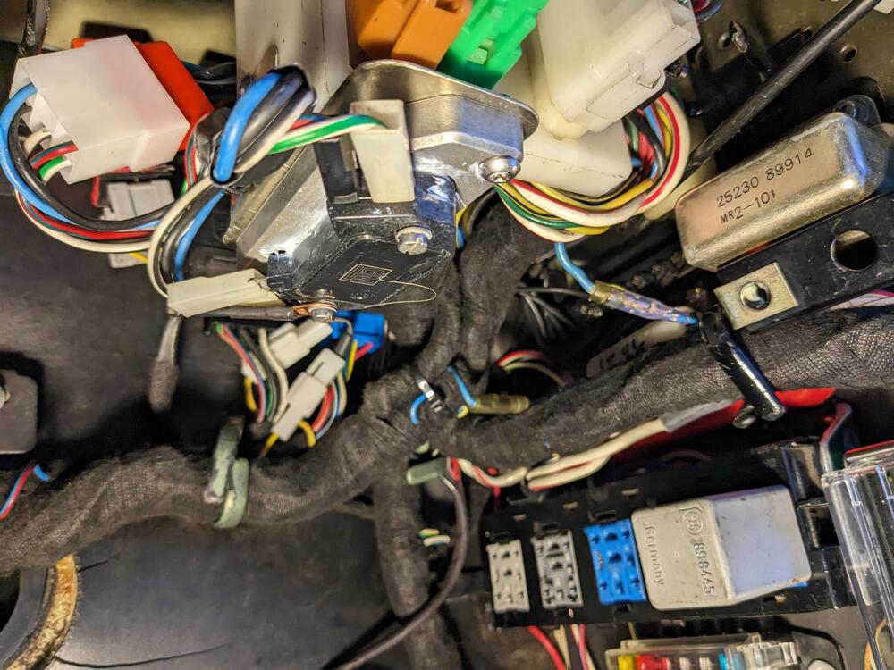
Since I had the under dash open again for the HEI module swap out, I cut the R/blk feed from the switch to the rear & fed that into a relay as the trigger signal (86). Switched power to the relay is the R/gy wire, 2nd from the right. No fuse in the pic yet. Output from the relay (87) then connected to the R/blk going to the rear lights. Used 6.3mm spades for the harness connections, M/F, so I can bypass the relay if needed for any reason. Maybe it's not as likely to fail with lower draw LEDs anyway.


Since I had the under dash open again for the HEI module swap out, I cut the R/blk feed from the switch to the rear & fed that into a relay as the trigger signal (86). Switched power to the relay is the R/gy wire, 2nd from the right. No fuse in the pic yet. Output from the relay (87) then connected to the R/blk going to the rear lights. Used 6.3mm spades for the harness connections, M/F, so I can bypass the relay if needed for any reason. Maybe it's not as likely to fail with lower draw LEDs anyway.

lookforjoe
True Classic
Bought a timer relay to use to prime the fuel pump. I found out that they don't provide a wiring schematic for the port designation, which doesn't match what I'm familiar with. Any input from our electronic wizzes? ")
CB (87, 87a?)
COM (switched or constant input?)
CK (87, 87a?
GND (ground)
IN (trigger or ?)
VCC (trigger or?)

CB (87, 87a?)
COM (switched or constant input?)
CK (87, 87a?
GND (ground)
IN (trigger or ?)
VCC (trigger or?)
Last edited:
ng_randolph
Bjorn H
Comparing the bottom traces of the PCB with the spec for the SRD-12VDC-SLC relay in the photo, it appears that:Bought a timer relay to use to prime the fuel pump. I found out that they don't provide a wiring schematic for the port designation, which doesn't match what I'm familiar with. Any input from our electronic wizzes?
CB (87, 87a?)
COM (switched or constant input?)
CK (87, 87a?
GND (ground)
IN (trigger or ?)
VCC (trigger or?)
View attachment 78550
COM corresponds to terminal 30 of standard Bosch style relays
CB -> 87a (Normally closed)
CK -> 87 (Normally open)
Which means that there should be continuity between COM and CB when the circuit is not powered; easy enough to verify.
And if the labeling follows normal nomenclature, GND is ground, VCC is positive supply voltage and IN is the trigger input.
Last edited:
lookforjoe
True Classic
Car ran fine today, no breakup under load. However, traffic was heavier so I didn't get to push it as hard as yesterday. I'll have to see how it goes over the next few days before I consider it resolved.
I got around to the horns today - I have needed hem several times when ppl (in SUV height vehicles) started to move into my lane without looking down. The horns were ****, to put it mildly, sounded like an anemic fart.
I made a sub harness incorporating the grounds needed for the Volvo horns, converted the spade feed to JPT, and put those in after work.
driver's side

pass side

grounds - factory horns ground through the body

I got around to the horns today - I have needed hem several times when ppl (in SUV height vehicles) started to move into my lane without looking down. The horns were ****, to put it mildly, sounded like an anemic fart.
I made a sub harness incorporating the grounds needed for the Volvo horns, converted the spade feed to JPT, and put those in after work.
driver's side
pass side
grounds - factory horns ground through the body
Last edited:
lookforjoe
True Classic
Comparing the bottom traces of the PCB with the spec for the SRD-12VDC-SLC relay in the photo, it appears that:
COM corresponds to terminal 30 of standard Bosch style relays
CB -> 87a (Normally closed)
CK -> 87 (Normally open)
Which means that there should be continuity between COM and CB when the circuit is not powered; easy enough to verify.
And if the labeling follows normal nomenclature, GND is ground, VCC is positive supply voltage and IN is the trigger input.
Thank you.
So, what's confusing to me is the VCC input. That is needed for the relay timer circuit to operate? I was thinking of it in terms of a standard relay where the only supply would be on 30 - but since this has a timer circuit, VCC is what governs that I'm assuming.
ng_randolph
Bjorn H
Yes, the timer part needs power to operate. Depending on how it behaves at startup, you may be able to connect VCC, IN and COM to ignition switched power, GND to ground and CK to the fuel pump. What might throw a wrench in this is that the timer may need to see the IN signal going from low to high after the timer circuit is powered up. One would hope that the timer retains the delay setting after powered is removed.Thank you.
So, what's confusing to me is the VCC input. That is needed for the relay timer circuit to operate? I was thinking of it in terms of a standard relay where the only supply would be on 30 - but since this has a timer circuit, VCC is what governs that I'm assuming.
lookforjoe
True Classic
Yes, the timer part needs power to operate. Depending on how it behaves at startup, you may be able to connect VCC, IN and COM to ignition switched power, GND to ground and CK to the fuel pump. What might throw a wrench in this is that the timer may need to see the IN signal going from low to high after the timer circuit is powered up. One would hope that the timer retains the delay setting after powered is removed.
I think it will work with the momentary input - little hard for me to decipher, however with the relay powered I can try to follow these steps below for mode 1 (of 4), prolly make more sense then
Last edited:
lookforjoe
True Classic
Installed the LED-compatible flasher relays today & switched out the front & rear directional bulbs
removed the two factory relays

used the flasher relay mount point for the grounds

made a stainless bracket to retain the relays. It is nice to be able to adjust the flasher speed

Cleaned up the housings, seals & lenses, and added a thin strip of closed cell foam to improve the seal. Also Volvo used nylon washers to help seal the screw holes, so I added those.


cleaned up the foam moisture pads & re-glued them


Relocated the fromt plate with a aluminum adaptor & cut off the two ears welded to the bumper. Added rivnuts & studs so I could use the Volvo acorn nuts

drilled the Skillard grille to secure the bracket to. Angles were all wrong to mount it to the bumper as designed


removed the two factory relays
used the flasher relay mount point for the grounds
made a stainless bracket to retain the relays. It is nice to be able to adjust the flasher speed
Cleaned up the housings, seals & lenses, and added a thin strip of closed cell foam to improve the seal. Also Volvo used nylon washers to help seal the screw holes, so I added those.
cleaned up the foam moisture pads & re-glued them
Relocated the fromt plate with a aluminum adaptor & cut off the two ears welded to the bumper. Added rivnuts & studs so I could use the Volvo acorn nuts
drilled the Skillard grille to secure the bracket to. Angles were all wrong to mount it to the bumper as designed
Attachments

Last edited: