
You are using an out of date browser. It may not display this or other websites correctly.
You should upgrade or use an alternative browser.
You should upgrade or use an alternative browser.
Selling the X & Bought an 75 Datsun 280Z
- Thread starter lookforjoe
- Start date
lookforjoe
True Classic
Electrolytically caps have a wide tolerance -20% / +50% or worse and are not used where precision is a requirement. Also, how they are measured and at what frequency will give different results, no need to be so precise when using them.
That's interesting to note. All I did to get the clock to work was swap the two new caps out with ones that measured closer to spec. Not sure whay that would be if the tolerance typically is not an issue. It could be that it was a problem because the resistors they add to the board vary in value (based on comments from the guy that rebuilds them), so perhaps the values they set are based on the actual cap value, vs. the rated?
dllubin
Don
If that clock relies on the value of an electrolytic capacitor to keep time, be sure to keep your wristwatch. They are popular for applications that don't require precision but need large values of capacitance at low frequencies. The most common application is power supply filtering.That's interesting to note. All I did to get the clock to work was swap the two new caps out with ones that measured closer to spec. Not sure whay that would be if the tolerance typically is not an issue. It could be that it was a problem because the resistors they add to the board vary in value (based on comments from the guy that rebuilds them), so perhaps the values they set are based on the actual cap value, vs. the rated?
lookforjoe
True Classic
If that clock relies on the value of an electrolytic capacitor to keep time, be sure to keep your wristwatch. They are popular for applications that don't require precision but need large values of capacitance at low frequencies. The most common application is power supply filtering.
The Z guy described the circuit flow - I can't reword it, so here it is:
" The 2M ohm resistor provides bias for transistor so it is almost turning on. The higher the resistor value the lower the voltage(bias) and the transistor might not turn on . The first coil detects the magnets on the flywheel as it passes and generates a small electrical pulse in the first winding. This pulse passes through the 10uF cap going to the base of the transistor and turns it on. Current then flows through the 2nd winding through the 680 ohm resistor. This current produces a small magnetic pulse which gives the magnets a "push" when they pass through the coil and keeps the flywheel turning."
dllubin
Don
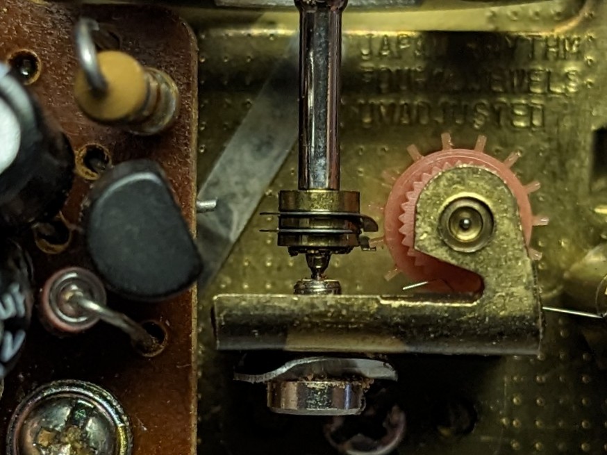
I went back and looked at the video again. What controls the timing of that clock is the balance wheel and the balance wheel spring. I think that all the circuit does is keep the main spring wound. I've repaired a number of 60s era car clocks and they operate very similar except the rewind pulse is created mechanically. The typical mechanism would drive a pair of electrical contacts together until two contacts (~30 sec.) meet and current is fed to a solenoid that pulls the contacts back away from each other while winding the main spring. The contacts would often become eroded, causing the clock to stop. If the circuit in your car eliminates the contacts, that is a good thing. I think what happened to your clock was that the circuit elements went so far out of spec that it could not function. It should not have any effect on the timing unless it can no longer wind the main spring. If the movement is clean, undamaged, and properly lubricated, it should work well. I used to restore antique clocks so I find the progression in car clock technology from what I used to work on to your Z clock interesting. Of course, a few years after your Z was built, most of the industry went to quartz clocks as they were more reliable, accurate, and cheaper.The Z guy described the circuit flow - I can't reword it, so here it is:
" The 2M ohm resistor provides bias for transistor so it is almost turning on. The higher the resistor value the lower the voltage(bias) and the transistor might not turn on . The first coil detects the magnets on the flywheel as it passes and generates a small electrical pulse in the first winding. This pulse passes through the 10uF cap going to the base of the transistor and turns it on. Current then flows through the 2nd winding through the 680 ohm resistor. This current produces a small magnetic pulse which gives the magnets a "push" when they pass through the coil and keeps the flywheel turning."
lookforjoe
True Classic
So, a little background. For my AC system control relay, I need a signal that ties into the charging circuit (D+61). On a Volvo, this would travel to the ground side of the idiot light, and ground through the alternator (D+61 terminal) when the engine is not running. Using this to get all my thoughts in one place...

As far as I can tell, there is no way to wire this to the alternator, as it doesn't have a equivalent connection
75 280Z

Volvo alternator, has an additional diode pack. I don't even know if using a later internally regulated Datsun alternator would fit the bill.

I read in another thread on ZClassic - that the L terminal of the V reg would serve to provide the charge indicator lamp circuit I need
The 1975 wiring diagram shows a wire connected to the L terminal, but it also shows a voltmeter, so I'm assuming that is an error
77 color diagram shows the wiring through to the voltmeter & charge indicator lamp


75 diagram - The wiring diagrams I have show a Blue or a Grey connected to the harness side of this. Following it through, it seems to go to the Interlock Relay (which my car doesn't have)


FSM shows a W/R wire connected to the L terminal though.

As far as I can tell, I should be able to run a wire from the w/r terminal into the cabin & use that to provide the ground circuit the AC relay needs to function
dllubin
Don
What is the signal that the control relay is expecting and under what conditions is it expecting it? Perhaps the signal could be derived in some alternate manner if it becomes a problem getting it from the Datsun alternator. I'm assuming that if it was easy to substitute a Volvo alternater for the Datsun alternator, you would have already done it. Any chance of swapping the Datsun regulator for the Volvo?
lookforjoe
True Classic
What is the signal that the control relay is expecting and under what conditions is it expecting it? Perhaps the signal could be derived in some alternate manner if it becomes a problem getting it from the Datsun alternator. I'm assuming that if it was easy to substitute a Volvo alternater for the Datsun alternator, you would have already done it. Any chance of swapping the Datsun regulator for the Volvo?
Thanks for the query Don
The Datsun has a fancy external regulator, that is rock solid. A Volvo one would not provide the leg I need. I'm going to investigate the actual wiring once the rain stops, hopefully on Sunday. I can wire a test lamp in the bay to confirm whether the L terminal works the same as the later Z's (pre-internal regulator)
This is the flow path for the Volvo AC relay trigger. I didn't review it before I wired the relay, I assumed it just needed a vBat signal once charging, which is obviously incorrect.
Based on this, it appears the relay trigger circuit grounds through alternator D+61 via the charge indicator lamp, then once charging there is no difference in potential, and relay switches to provide output on 87 to AC thermostat
lookforjoe
True Classic
The quality of the movement seems quite high - I put some pics in this post - everything is clean & moves freelyI went back and looked at the video again. What controls the timing of that clock is the balance wheel and the balance wheel spring. I think that all the circuit does is keep the main spring wound. I've repaired a number of 60s era car clocks and they operate very similar except the rewind pulse is created mechanically. The typical mechanism would drive a pair of electrical contacts together until two contacts (~30 sec.) meet and current is fed to a solenoid that pulls the contacts back away from each other while winding the main spring. The contacts would often become eroded, causing the clock to stop. If the circuit in your car eliminates the contacts, that is a good thing. I think what happened to your clock was that the circuit elements went so far out of spec that it could not function. It should not have any effect on the timing unless it can no longer wind the main spring. If the movement is clean, undamaged, and properly lubricated, it should work well. I used to restore antique clocks so I find the progression in car clock technology from what I used to work on to your Z clock interesting. Of course, a few years after your Z was built, most of the industry went to quartz clocks as they were more reliable, accurate, and cheaper.
lookforjoe
True Classic
When the rain stops, hopefully Sunday - I'll look at the actual v/reg harness plug & see if I can wire a test lamp to the L circuit. Should be easy enough to determine from there if it will suit my needs. Thanks to SteveJ on ClassicZ for pointing out the L terminal in another thread.
from page EE-14:

lookng through my earlier pics - I do have an empty spot in the v/reg harness for the L terminal

thinking about the actual lamp - I can repurpose the non-functional low fuel indicator. I'll cut the Bl/Y wire back in the harness & connect that to the L terminal & Blk/Wh wire at my AC relay.


I've taken a Volvo seat belt warning lamp & sanded off the symbol, so I can fit that in the console for the charge indicator lamp

I also have some old fog lamp switches, the 75 was pre-wired for fog lamps (spade connector below), so maybe I'll add some fog or driving lamps behind the lower grille


from page EE-14:
lookng through my earlier pics - I do have an empty spot in the v/reg harness for the L terminal

thinking about the actual lamp - I can repurpose the non-functional low fuel indicator. I'll cut the Bl/Y wire back in the harness & connect that to the L terminal & Blk/Wh wire at my AC relay.
I've taken a Volvo seat belt warning lamp & sanded off the symbol, so I can fit that in the console for the charge indicator lamp

I also have some old fog lamp switches, the 75 was pre-wired for fog lamps (spade connector below), so maybe I'll add some fog or driving lamps behind the lower grille
Last edited:
lookforjoe
True Classic
So, now that the ambient temps have dropped, I see that the cold start system is not actually operational. When I rewired the EFI harness I found the ECT & TTS were mis-wired. I don't know if that caused an issue at the ECU.

In any event, I bridged the TTS connector, and have voltage output from the EFI relay 86 terminal to the cold start valve when cranking (checked with test lamp on pin 86 at relay, and 45 at CSV.) I confirmed the CSV functions by powering & grounding the CSV to the battery with the fuel system pressurized.
The CSV does not inject fuel however, and if I put the test light across the pins of the connector, it does not light, which would indicate to me that the ground side of the circuit is non-functional. I tested the continuity of the harness from the TTS connector (pin 46) and the CSV connector (pin 46) and both have continuity back to the harness plug I made.
Tomorrow I'll have to check the continuity of the ground side of the harness from there back to the ECU connector.
The wiring diagram is not accurate in terms of the actual wiring of this circuit - the bridge circuit for the TTS in not at the CSV, is it back in the harness on the inner fender, where 47 is T'd off into to 45 wires, and 21 is T'd into 2 46 wires. I discovered that when I did the re-wiring.

lookforjoe
True Classic
Did the AC relay signal re-wire using the L terminal and repurposed the low fuel lamp for the charge indicator lamp. Works as expected.
V/reg connector, with wh-bl connected

while I was in the bay I repurposed unused AC system wires and moved them to the engine harness connector for Oil temp sender (Bl-Wh) and to the alternator for Voltmeter (Y-R)

I need a spot for the charge indicator lamp, so I removed the massive "Rear Defogger" lamp & fitted a red lens, then added a bulb socket plate to the rear defogger switch, similar to what the Hazard switch has. I had to cut a hole in the rear defogger & add a color plate w/icon for the defogger

re-drilled the backside to accept a bulb socket w/spade terminals

making the bulb plate

marked area to be cut out

build plate fitted


illuminated

Last thing, the 1363449 AC relay is dead - I re-flowed the solder joints, but it still doesn't switch after the 10sec delay, so I have ordered another

Last edited:
lookforjoe
True Classic
Still back & forth with the cold start circuit. I have continuity in the harness from 21 at the ECU to the CSV & TTS. The factory test is to disconnect the ECU connector & use a voltmeter on pin 21 - if there is battery voltage when cranking, the circuit has integrity.So, now that the ambient temps have dropped, I see that the cold start system is not actually operational. When I rewired the EFI harness I found the ECT & TTS were mis-wired. I don't know if that caused an issue at the ECU.
In any event, I bridged the TTS connector, and have voltage output from the EFI relay 86 terminal to the cold start valve when cranking (checked with test lamp on pin 86 at relay, and 45 at CSV.) I confirmed the CSV functions by powering & grounding the CSV to the battery with the fuel system pressurized.
The CSV does not inject fuel however, and if I put the test light across the pins of the connector, it does not light, which would indicate to me that the ground side of the circuit is non-functional. I tested the continuity of the harness from the TTS connector (pin 46) and the CSV connector (pin 46) and both have continuity back to the harness plug I made.
Tomorrow I'll have to check the continuity of the ground side of the harness from there back to the ECU connector.
The wiring diagram is not accurate in terms of the actual wiring of this circuit - the bridge circuit for the TTS in not at the CSV, is it back in the harness on the inner fender, where 47 is T'd off into to 45 wires, and 21 is T'd into 2 46 wires. I discovered that when I did the re-wiring.
I did that, and got the desired result. However, the CSV does not fire, even though I know the valve is functional when wired independently of the circuit.
What I'm having trouble with is the way it's all wired - looking at the diagram, it appears the TTS is in parallel, not series, so HTF it would interrupt the current to the CSV? Makes no sense to me. The reality of the circuit wiring is thus:
Further investigation is needed.
kmead
Old enough to know better
You will miss the low fuel light. Our Miata doesn’t have one and there have been many time when I have driven it and looked down to see there is almost no fuel (10 gallon tank doesn’t go far even at 29 mpg average in daily commuting).Did the AC relay signal re-wire using the L terminal and repurposed the low fuel lamp for the charge indicator lamp.
It is a minor but useful feature.
lookforjoe
True Classic
You will miss the low fuel light. Our Miata doesn’t have one and there have been many time when I have driven it and looked down to see there is almost no fuel (10 gallon tank doesn’t go far even at 29 mpg average in daily commuting).
It is a minor but useful feature.
It didn't work anyway - the circuit burns out in the sending unit. I still have the wiring to the sender tucked away, so if I have to replace the sending unit DTR I'll re-wire a indicator. The dealer threw out the indicator when they added AC. The bulb holder was laying behind the console. The CAT & Floor temp indicators are available, just takes more work to use them as they have a common ground with other circuits, which is why I didn't do it now..
Last edited:
ng_randolph
Bjorn H
The TTS (at least on the L-Jetronic, which I believe the Z uses a licensed copy of) is a three terminal device with ground through the body. As I understand your schematics, 47 (and 45) gets battery voltage while cranking the starter. Thus one side of the CSV gets battery voltage, as does one side of the heater inside the TTS. 46 is grounded to body ground through the switch internal to the TTS - until the TTS heats up and the ground connection is interrupted. My guess is that 21 is either an output from the ECU, allowing the ECU to extend the CSV open-time beyond what the TTS allows, or it is an input to the ECU, letting the ECU know that the CSV is active.Still back & forth with the cold start circuit. I have continuity in the harness from 21 at the ECU to the CSV & TTS. The factory test is to disconnect the ECU connector & use a voltmeter on pin 21 - if there is battery voltage when cranking, the circuit has integrity.
I did that, and got the desired result. However, the CSV does not fire, even though I know the valve is functional when wired independently of the circuit.
What I'm having trouble with is the way it's all wired - looking at the diagram, it appears the TTS is in parallel, not series, so HTF it would interrupt the current to the CSV? Makes no sense to me. The reality of the circuit wiring is thus:
View attachment 77732
Further investigation is needed.
The few failures I have seen with the Bosch TTS is that the switch contact resistance becomes excessive so the CSV does not turn on.
Last edited:
lookforjoe
True Classic
New probelm - I ran the motor yesterday & used the timing light to check base & advance, leaned over & revved the motor. Timing advances as expected when revved, and sits at approx 8º BTDC at idle.
The problem is the motor now goes completely flat when revved & held at around 2500-3K. Fuel pressure does not falter, I have a line gauge after the filter.
Other ppl have had issues with the HEI module conversion where it does not want to rev.
I tried reversing the wires from the distributor reluctor, and that had very bad results. It cranked normally for a few revolutions, then turned over very slowly, then not at all. After that, it was completely dead. I thought the battery was drained - I found that cranking like that blew the 125 Amp fuse breaker on the starter cable from the battery. I replaced that, put the wires back & it started again normally.
I don't understand why the ignition system is creating such an extreme current draw when the reluctor wires are switched. No one has previously mentioned any issues with reversing the reluctor wires.
I tried another coil, in case that was an issue.
I'm going to put the stock module and coil back in & confirm whether the issue is with the HEI conversion or not.
re-wired to plug into the modded harness

lookforjoe
True Classic
Thank you Bjorn! Now that you point it out - I see that (the body ground in the TTS) - so that now makes sense. When Datsun indicates circuit testing in the manual, it seems it is only to verify that the wiring. I'll have to reattach the TTS & see if it works after I check that it has continuity when cold.The TTS (at least on the L-Jetronic, which I believe the Z uses a licensed copy of) is a three terminal device with ground through the body. As I understand your schematics, 47 (and 45) gets battery voltage while cranking the starter. Thus one side of the CSV gets battery voltage, as does one side of the heater inside the TTS. 46 is grounded to body ground through the switch internal to the TTS - until the TTS heats up and the ground connection is interrupted. My guess is that 21 is either an output from the ECU, allowing the ECU to extend the CSV open-time beyond what the TTS allows, or it is an input to the ECU, letting the ECU know that the CSV is active.
The few failures I have seen with the Bosch TTS that the switch contact resistance becomes excessive so the CSV does not turn on.
Ics19
belle macchine!
Not sure of your whole system, but the typical reluctor output looks like this:I don't understand why the ignition system is creating such an extreme current draw when the reluctor wires are switched. No one has previously mentioned any issues with reversing the reluctor wires.
Distributor options
Not sure how do I find out I'm beginning to think I am still missing something or bought the wrong dizzy maybe one that might need a sensor
xwebforums.com
There does seem some poor generic modules around, and trigger nothing like the original GM ones did from the 70s/80s. What seems to be happening with people trying to rebuild the fiat/lancia/ferrari coil pack is that some new modules don't trigger consistently and the cut-off for the spark point shifts out as rpm increases. I'd check your timing at 2k and 3k - it's highly likely your timing is retarding as the revs increase by as much as 10 or more degrees, even though your distributor centrifugal advance has kicked in

lookforjoe
True Classic
Not sure of your whole system, but the typical reluctor output looks like this:
The coil dwell (charge) is triggered on the rising signal (typically only 3ms) and the sharp drop in the trace is the cut-off for the spark. Reversing the pickup makes the signal upside down, so I'm guessing you're getting a very long dwell time (i.e. unnecessarily saturated) and then a poor switch for the spark.Distributor options
Not sure how do I find out I'm beginning to think I am still missing something or bought the wrong dizzy maybe one that might need a sensorxwebforums.com
There does seem some poor generic modules around, and trigger nothing like the original GM ones did from the 70s/80s. What seems to be happening with people trying to rebuild the fiat/lancia/ferrari coil pack is that some new modules don't trigger consistently and the cut-off for the spark point shifts out as rpm increases. I'd check your timing at 2k and 3k - it's highly likely your timing is retarding as the revs increase by as much as 10 or more degrees, even though your distributor centrifugal advance has kicked in
Thank you for the insight. That does sound highly plausible, given the symptom. I bought a Standard Motor Product version off RockAuto - I'll confirm the issue by putting the factory parts back, if that resolves it, then I'll order a AC Delco version.