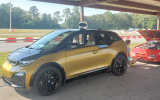
The X1/9e. Conversion of a 1983 X1/9 - my own since 1993 - to electric

Ideal for weight distribution, I agree. But I wasn't able to find battery packs that would fit in there. There is a major difference betweeten both spaces: one belongs to the passenger cabin and the other not. First step would be to separate the whole space from the passenger cabin and not only with the original cover in front of the spare wheel. Why? In case of a battery failure, temperatur and pressure inside the battery pack could increase very fast which opens the burst valve to the outside. After separating you have to find a way to access this space and even load your modules to it.
Using the fuel tank space only could be an idea, if you find the right battery modules for this area. You might be able to place around 12 - 16 kWh of batteries there, good for a 100 km drive. Mine -2nd hand from a Tesla Model S- wouldn't fit, they're just too long. I use this space for charger and DC/DC converter. Together, both use the surface where the fuel tank has been and a lot of unused space for air circulation remains :(
May the next project find better battery modules ;)
The space of the spare wheel is used for the HV distribution box and additional LV distribution. This place is easy to access, is dry and has room for additional equipment like a Notebook for fine tuning.
If one were to change the fuel tank area and the spare tire area into one contiguous space it would likely be wide enough as it effectively goes from outside panel to outside panel of the car. Leaving appropriate openings where the fuel tank is removed could allow for air circulation but one could also run air in from the side vents which are accessible to the spare tire area (Today separated by chip board panel).

Closing the spare tire well off is just some sheet metal and rivets away from being done. Removing the separating panel between the spare tire well and the fuel tank area would be minor surgery. There are existing channels from the spare tire area to the trunk on either side over the wheel arches for large cables. There is a sizable opening at the right side of the trunk for cables into the motor bay.

Cables could go from the spare tire area, over the wheel arch to the trunk, to the controller and then to the motor bay.

The controllers could be in a housing off of the trunk, using the engine bay access plate as the access point to the controllers in their own box. This way one isn’t digging around behind a seat to work on it, adjust wiring etc. and could be laid out full width of the trunk and be within the wheel bays of the rear wheels.

All highly protected areas of the car. This would place all of the components within the wheel base and hopefully as low as possible short of the rollerskate platform…
Didn't you forget the middle tunnel? Maybe It could be cut out or at least shinked to the minimum, but it reduces the height of that space and lifts the centre of gravity. And still both spaces wouldn't have the same depth, because the fuel tank expands into the engine bay and the spare wheel doesn't.
But you are 100% correct. I'm pretty sure a good mechanic or at least a more skilled person than I would come to a much better solution. Even if he the chooses the same battery modules. As an electronic engineer I'm focused more on reducing the amount of work on the mechanical side and can hardly wait to program the HMI's and tune the drive itself. At the moment I'm running the 3D printer 24 hours for parts like this one below. A simple frame for a little display, but I wanted to integrate the original clock and the fan control to respect the original design. The size is close to the maximum of my 3D printer which doesn't make it easier to get an aceptable result.
20230116_184149.jpg
 
Didn't you forget the middle tunnel? Maybe It could be cut out or at least shinked to the minimum, but it reduces the height of that space and lifts the centre of gravity. And still both spaces wouldn't have the same depth, because the fuel tank expands into the engine bay and the spare wheel doesn't.
But you are 100% correct. I'm pretty sure a good mechanic or at least a more skilled person than I would come to a much better solution. Even if he the chooses the same battery modules. As an electronic engineer I'm focused more on reducing the amount of work on the mechanical side and can hardly wait to program the HMI's and tune the drive itself. At the moment I'm running the 3D printer 24 hours for parts like this one below. A simple frame for a little display, but I wanted to integrate the original clock and the fan control to respect the original design. The size is close to the maximum of my 3D printer which doesn't make it easier to get an aceptable result.
View attachment 69757
Yes you would want to avoid the tunnel but it really doesn’t rise that much. But yes it would raise the battery in any case.

Like all these things it’s engineering and compromises to get to the best solution within the limitations of the problem. For me it’s entirely academic, for you it’s a real problem. You are the one solving it. :)

There is nothing sacrosanct about the firewall aside from carrying the glass and being part of the the structural membrane across that part of the car. Making it deeper would be fairly simple, the electric motor is not very big and mounted quite low, particularly if one moved away from the X transmission.


I don’t have a good sense of the battery packs and how they are arranged so it could all be moot.
 
The center tunnel along with the center console/dash bracing is a structural element. I'd be careful about modifying it too much.
 
Ideal for weight distribution, I agree. But I wasn't able to find battery packs that would fit in there. There is a major difference betweeten both spaces: one belongs to the passenger cabin and the other not. First step would be to separate the whole space from the passenger cabin and not only with the original cover in front of the spare wheel. Why? In case of a battery failure, temperatur and pressure inside the battery pack could increase very fast which opens the burst valve to the outside. After separating you have to find a way to access this space and even load your modules to it.
Using the fuel tank space only could be an idea, if you find the right battery modules for this area. You might be able to place around 12 - 16 kWh of batteries there, good for a 100 km drive. Mine -2nd hand from a Tesla Model S- wouldn't fit, they're just too long. I use this space for charger and DC/DC converter. Together, both use the surface where the fuel tank has been and a lot of unused space for air circulation remains :(
May the next project find better battery modules ;)
The space of the spare wheel is used for the HV distribution box and additional LV distribution. This place is easy to access, is dry and has room for additional equipment like a Notebook for fine tuning.
Thanks. Maybe with time more battery modules will become available. If I ever start down this road I assume a key decision is how much range to target.
 
Thanks. Maybe with time more battery modules will become available. If I ever start down this road I assume a key decision is how much range to target.
Yeah, that's one of the main decisions to make. Power is the 2nd, but that's easier. You have to choose between A='like before', B='better' and C= 'awesome'. It is a matter of money as always.
A could be the parts of a wracked Chevy Bolt and you could get something like this: Electric Deloren - great project btw.
B maybe my approach? The best batteries combined with a great motor - I'm just dreaming...
C get a Tesla drive train and matching batteries - it couldn't be better
The European market wasn't ready for a conversion like A when I started my project one year ago. Most of the cheaper cars have rented batteries - like our Renault ZOE - and I was afraid of the lack of detailled information by the car manufactors for single parts, connectors, communication protocolls, ... . B looked like the easier option, we will see. C was out of my budget.
 
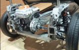
Since I got my X1/9 a month ago I've thought of how fun it would be with the drivetrain out of our BMW i3s. 185h and 200lbft of instant torque....
One big problem with using an i3 motor/single speed gearbox (relatively compact, but far offset in i3 for the optional "Range Extender" gas genset) is that with X1/9-typical 69" tire circumference (165/70R13) vs 88" for the i3 (185/55R20) top speed would be reduced from 100mph to ~80mph. Acceleration, however, would be brutal!
I'd be careful mounting batteries in the spare tire or fuel tank areas - would need strong bracing to protect passengers in a front end collision. Presumably the fuel tank area is already braced but certainly not the spare tire area.
When we converted a Ford Fiesta to electric as an Engineering school project in the mid 90s I designed and built the "cages" for the lead acid batteries behind the seats. Motor connected to the stock transmission, with clutch, and it worked quite well.
Anyway, following this thread - keep up the good work!!
1674099120930.pngScreenshot 2022-03-05 12.17.07 PM.pngScreenshot 2021-10-12 6.31.49 PM.png
 
Since I got my X1/9 a month ago I've thought of how fun it would be with the drivetrain out of our BMW i3s. 185h and 200lbft of instant torque....
One big problem with using an i3 motor/single speed gearbox (relatively compact, but far offset in i3 for the optional "Range Extender" gas genset) is that with X1/9-typical 69" tire circumference (165/70R13) vs 88" for the i3 (185/55R20) top speed would be reduced from 100mph to ~80mph. Acceleration, however, would be brutal!
I'd be careful mounting batteries in the spare tire or fuel tank areas - would need strong bracing to protect passengers in a front end collision. Presumably the fuel tank area is already braced but certainly not the spare tire area.
When we converted a Ford Fiesta to electric as an Engineering school project in the mid 90s I designed and built the "cages" for the lead acid batteries behind the seats. Motor connected to the stock transmission, with clutch, and it worked quite well.
Anyway, following this thread - keep up the good work!!
View attachment 69819View attachment 69821View attachment 69822
The spare tire area is within the structural hoops of the rest of the engine bay etc.

There are few areas of the car as well protected from intrusion as that zone of the car. The area just behind your seat is the strongest part of this car with the greatest concentration of structure. The frunk is also well structured behind the strut towers with intentional and considerable crush zone forward of the strut towers. In the rear you have a primary crush zone in the trunk structure and then a very strong box in the engine bay from the strut towers forward and then the targa area which starts with the structure at the bottom in a ring which then progresses upward with the targa bar.

That said, having the spare tire well sealed and properly closed off from the passenger compartment would be critical just as it is with the gas tank (though the speaker openings have always given me pause there).

If the car crushed to the point of damaging the zone between the targa structure and forward of the engine bay structure ring, there really wouldn’t be much any emergency personnel could do for you aside from enjoy your Viking funeral on your way to Valhalla.
 
I'm talking about the battery/ies continuing forward into the occupants' backs in case of front end collision, but you're right in an X1/9 vs typical modern vehicle head on collision that would just be one of many likely modes of fatality.
 
I'm talking about the battery/ies continuing forward into the occupants' backs in case of front end collision, but you're right in an X1/9 vs typical modern vehicle head on collision that would just be one of many likely modes of fatality.
Aaah, yes properly restraining a lot of mass is an issue. If one were placing the batteries there one would want to ensure they are properly restrained. Definitely something which can be managed.
 
Maybe something for the 'what have you done to your X today' section...
I've replaced the 'fuel reserve indicator' with an OLED display. It will be used for other status information from the inverter. It fits quite well without further modifications even if a few lines are no more visible.
20230123_112743.jpg
 
Maybe something for the 'what have you done to your X today' section...
I've replaced the 'fuel reserve indicator' with an OLED display. It will be used for other status information from the inverter. It fits quite well without further modifications even if a few lines are no more visible.
View attachment 69987
That’s impressive. Looks like it’s always been that way.
 
Maybe something for the 'what have you done to your X today' section...
I've replaced the 'fuel reserve indicator' with an OLED display. It will be used for other status information from the inverter. It fits quite well without further modifications even if a few lines are no more visible.
View attachment 69987
One could imagine it being in the position of the Bertone sign, perhaps offering other status info as well as Bertone.
 
One could imagine it being in the position of the Bertone sign, perhaps offering other status info as well as Bertone.
That was my first choice, but you would have to cut out more of the flasher lightbox or use an even smaller display.
For the reserve light you just have to replace the orange filter by the display -> done.
 
It's freezing cold outside in my Garage and I haven't finished all the wiring yet. Summer was too hot / short or both ;-)
It's time for documentation ;-(. At first I added and changed some switches: The gearchange lever should be removed as soon as I made some test drives. Clutch is also gone as you can see. My plan is to drive the car in 3rd gear all the time. One R-N-D switch in the center console is all that will remain to operate it. I do love strong recuperation of the electric motor that allows one-pedal-drive. There are situations you like to switch it off to set the car into sailing mode. Therefor the "RECUPERATION OFF" switch.
The heater is directly powered by the HV-battery and you have to switch it on separately. It is not reduced to the front window and you can still open the other vents, but that will be my main use of it as it is a TUEV requirement.
Dashboard.png
 
Perhaps obtain the drive selection buttons from a 1st generation Fiat 500e for your PRND switch. Keeping it Italian that way!
 
Tbh, I didn't know what to do with the P. The motor doesn't have an internal brake and the X hasn't got an electric parking brake. P would be the same as N and the latter reminds you to always use the mechanical park brake.
At least the inverter is Made in Italy. Doesn't it fit nicely? The electric side dry behind the cover and the water cooling plate on the back faces the engine compartment.
20231116_133535.jpg
 
We had unsusual 13°C / 55F today and I took the chance to go in my garage. The header arrived around new year and I started to install it.
What a perfect fit :)! The space and the cover looks like it's made for it. The header tank is nothing special, just a 20 Euro Aliexpress part. Later it will support the cooling of the battery packs. A vertical transparent hose on front should visualize the fil level.

20240124_154526.jpg
header.jpg
 
I haven't had the same luck with another job that had to be done: Exchange the master brake cylinder. The problem wasn't the cylinder itself, but the lines on top. I recognized rust on one of them and ordered replacements. As soon as they arrived I found out that I've ordered the wrong fittings. I got M10 x 1.0 that is the common size today, but for FIAT M10 x 1.25 should fit.
20240122_160800.jpg
 
Back
Top