As promised before, here are some pictures of the pump in its final position.

One of the hoses is quite simple, a straight shot to the OEM coolant feed pipe. The second hose for the pump inlet isn't so friendly and will require a Z shaped hose in order to line up.

I was able to get some hoses from the auto parts store that I may be able to get to work.

Ignore the crappy sheet metal bracket, it was thrown together in less than an hour as a way to determine final dimensions for the plastic final product, whenever that becomes the priority over getting the electronics and routing sorted first.

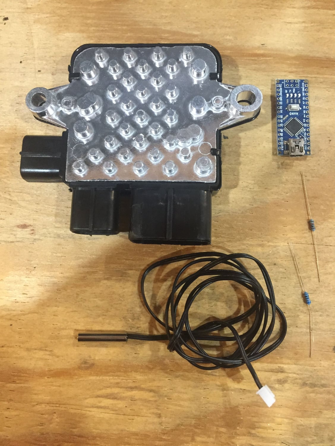
Last night I also got the pump controller harness made. I made a slight change to my initial plan of using the oil pressure switch as the engine on/off signal. Instead, (thanks to a suggestion from someone, maybe kmead) I'll be using the fuel pump power signal.

This way, as soon as the starter engages, the after run function cancels so that the cooling system does not try to pull a lot of power while the starter is engaged.

The controllers after run strategy uses high cooling power (fans and pump) for a short period of time, rather than a longer time period with lower speed, so I wanted to make sure the starter would not have to fight for power alongside the fans and pump.
PXL_20220624_221411781.jpg
PXL_20220624_221408210.jpg
 
Shouldn’t you move it over to have the intake directly inline with thermostat housing output which would put the output almost directly inline with the cross tube.

21422D57-FA66-478B-837D-81C784B47715.jpeg

BC546A8F-FF06-4BB2-BDEB-CE1462B73A48.jpeg
 
That's what I hoped to do originally, but for a number of reasons I settled on body mounting the pump instead. Hopefully this does an okay job at helping visualize it without seeing it in person.


That's what I hoped to do originally, but for a number of reasons I settled on body mounting the pump instead. Hopefully this does an okay job at helping visualize it without seeing it in person.


Thank you for taking the time, the video was an excellent way to have the ’discussion’, it clearly brought the issues across with minimal confusion.

Makes sense. I had forgotten the cross tube inlet was at the same plane as the thermostat outlet.

Moving the charcoal canister is not that big a deal. There is a mounting area behind it you could take advantage of.

How are you going to route the heater core return into the pump? Find a hose with a secondary hose as part of the assembly and use an inline connector to mate the return to it? I see lots of hoses like that on modern cars like my VW Golf etc

MWB offers a cross tube with no inlets which might serve better or one could cap the heater return nipple.

Remote mounting the unit is good as it will insulate it from vibration, the negative is you need sufficient room for the hoses to take the twisting relative to the motor’s motion. I had thought about changing the cross tube into a 90° at the old pump housing pointing towards the rear of the car and then have a new cross tube run across the structural rail at the back of the engine bay with flexible hose going from that to the 90. This is predicated on using a tube type header versus the convoluted down pipe our late cars come with as that transition would want to happen near the outlet zone for the exhaust downpipe on the bulkhead.

I will say that a sheet metal bracket could be more resistant to vibration and won’t suffer from sag under long term load as most plastics creep (though the fiber reinforced versions do this much less).

By the way I ran across this controller video, pertains

Again, thank you for taking the time. System design is always fun :)
 
Suppose somebody wanted to use the Pierburg EWP, but was not concerned with controlling everything as precisely as you propose to. If the EWP were just standing in for an engine driven pump with everything else remaining the same, how might one power and control the pump? Could it be done as simply as providing power to the pump?

I am interested, but I am not the one to build a control system for it. Alternatively, are you interested in selling a control system, once you have built it, to another forum member?
 
Thank you for taking the time, the video was an excellent way to have the ’discussion’, it clearly brought the issues across with minimal confusion.

Makes sense. I had forgotten the cross tube inlet was at the same plane as the thermostat outlet.

Moving the charcoal canister is not that big a deal. There is a mounting area behind it you could take advantage of.

How are you going to route the heater core return into the pump? Find a hose with a secondary hose as part of the assembly and use an inline connector to mate the return to it? I see lots of hoses like that on modern cars like my VW Golf etc

MWB offers a cross tube with no inlets which might serve better or one could cap the heater return nipple.

Remote mounting the unit is good as it will insulate it from vibration, the negative is you need sufficient room for the hoses to take the twisting relative to the motor’s motion. I had thought about changing the cross tube into a 90° at the old pump housing pointing towards the rear of the car and then have a new cross tube run across the structural rail at the back of the engine bay with flexible hose going from that to the 90. This is predicated on using a tube type header versus the convoluted down pipe our late cars come with as that transition would want to happen near the outlet zone for the exhaust downpipe on the bulkhead.

I will say that a sheet metal bracket could be more resistant to vibration and won’t suffer from sag under long term load as most plastics creep (though the fiber reinforced versions do this much less).

By the way I ran across this controller video, pertains

Again, thank you for taking the time. System design is always fun :)
I'm glad the video conveyed the point well- I've been wanting to do videos for a long time but I always make one mistake that scraps the video (without editing anyway) and sometimes circumstances change before I post so I just discard it.

Anyway. A part of the decision to mount it off to the side when body mounting the pump is that the engine mainly moves fore and aft in the engine bay due to the torque reaction from the transaxle- so if the pump was in line with that axis of movement but moves relative to the engine, there would have to be some solution for hose routing that allows for compliance.

By mounting the pump to the side, the movement relative to one another will not cause complete tension or compression on the hoses- and the longer hose run required will greatly help absorb compliance, even with the stainless intermediate pipe I am about to explain:


The pump outlet is easy...straight hose. Finding a perfectly fitting pump inlet pipe is a bit harder. I may cut off the two 90deg bends off of the hose I already got, and use a stainless pipe in between which also provides a place to put the heater return. It could also be routed to the thermostat housing with a bit of shuffling around of the many things on the housing- but I haven't gotten there yet. That'll come :)

As always Karl, thanks for the support and input! Also, I just noticed you work for Steelcase. Our formula team has been absolutely gawking over y'alls chairs as replacements for the 40 year old...things...we have in our office now. Do y'all do sponsorships? 😂 Joking of course....I think we may have actually worked out a deal with them provided we can come pick them up.
 
Last edited:
Suppose somebody wanted to use the Pierburg EWP, but was not concerned with controlling everything as precisely as you propose to. If the EWP were just standing in for an engine driven pump with everything else remaining the same, how might one power and control the pump? Could it be done as simply as providing power to the pump?

I am interested, but I am not the one to build a control system for it. Alternatively, are you interested in selling a control system, once you have built it, to another forum member?
So, if you want it to run at a set speed, based on the documentation it is plausible you could give the pump a switched/ign/relayed +12v and Gnd, and use a resistor between the 12v pin and PWM pin to set a continuous duty cycle. The relay could be triggered by the fuel pump power wire as to only come on when the engine is on... if FI anyway. Otherwise an inverted oil pressure switch signal would work.

In order for the pump to wake up, it needs a certain minimum duty cycle for a certain period of time- so you'd need to size the resistor to provide that at minimum. I believe the pump will accept a continuous DC voltage and treat 0-12v as 0-100% duty cycle based on my testing.

If you wanted to take it a step further with two speed control, you could use a thermoswitch on the tstat housing to bypass the aforementioned resistor above a certain temperature and send the pump to 100% duty cycle (emergency run mode/nearly full speed) to help cool the engine if things get out of hand. I would set this temperature high enough that it never triggers during normal operation as you'd essentially end up in a never ending oscillation otherwise...say 220f or thereabouts.

As far as selling/giving away and such: yes of course. Anything I spend time developing, I want to provide to the community as a resource. I would most definitely charge nothing for the CAD models, or any software related work I've done. I could theoretically compile Pierburg pump conversion kits together and sell them as a kit with all of the printed or manufactured parts- but that may be a bit ambitious considering time limitations. Of course, if I offer something it'll be tested for some duration of time first...I don't want to give y'all something crappy. :)

The controller is kind of on pause as I decided to go with the Tecomotive tinyCWA controller. The coding became simply too complex for someone of my level. Despite the actual task of the program being quite simple, implementing the sensor (v_in to temperature) translations and implementing the physical additional hardware needed to do it with an arduino turned out to beyond my capacity for the time being. Sorry to disappoint as I was hoping to be able to provide a cheap, effective, and as close to perfect (as possible) controller for y'all.

I will still do a fan controller with an arduino at some point as that is much cheaper, and code is avaliable online...I believe on some LS forums. Can I link another forum here? I know some communities have rules on that but if not I can share the fan control info I've managed to find if you're interested.
 
Last edited:
So, if you want it to run at a set speed, based on the documentation it is plausible you could give the pump a switched/ign/relayed +12v and Gnd, and use a resistor between the 12v pin and PWM pin to set a continuous duty cycle. The relay could be triggered by the fuel pump power wire as to only come on when the engine is on... if FI anyway. Otherwise an inverted oil pressure switch signal would work.

In order for the pump to wake up, it needs a certain minimum duty cycle for a certain period of time- so you'd need to size the resistor to provide that at minimum. I believe the pump will accept a continuous DC voltage and treat 0-12v as 0-100% duty cycle based on my testing.

If you wanted to take it a step further with two speed control, you could use a thermoswitch on the tstat housing to bypass the aforementioned resistor above a certain temperature and send the pump to 100% duty cycle (emergency run mode/nearly full speed) to help cool the engine if things get out of hand.

As far as selling/giving away and such: yes of course. Anything I spend time developing, I want to provide to the community as a resource. I would most definitely charge nothing for the CAD models, or any software related work I've done. I could theoretically compile Pierburg pump conversion kits together and sell them as a kit with all of the printed or manufactured parts- but that may be a bit ambitious considering time limitations. Of course, if I offer something it'll be tested for some duration of time first...I don't want to give y'all something crappy. :)

The controller is kind of on pause as a decided to go with the Tecomotive tinyCWA controller. The coding became simply too complex for someone of my level. Despite the actual task of the program being quite simple, implementing the sensor (v_in to temperature) translations and implementing the physical additional hardware needed to do it with an arduino turned out to beyond my capacity for the time being. Sorry to disappoint as I was hoping to be able to provide a cheap, effective, and as close to perfect (as possible) controller for y'all.

I will still do a fan controller with an arduino at some point as that is much cheaper, and code is avaliable online...I believe on some LS forums. Can I link another forum here? I know some communities have rules on that but if not I can share the fan control info I've managed to find if you're interested.
The only real rules we have are to not be a a~~hole. Well except for me, they give me carte blanche :) oh crap here comes Jim with the ban hammer…
 
Aight:


I finally got the engine mount debacle over today. I guess I'll drop more details about that in the snail mount thread. Moral of the story: check your work before you assemble everything :)

So, regarding the cooling system which I haven't done too much with, admittedly.

The delay-off relay came in from Del City Electronics. It is a Beuler BU-509TD in case anyone is interested in one. It's rated for 20/30A (20 amps for the normally closed circuit, 30amps for the normally open circuit, and has an adjustable delay off range between 2 seconds and 3 minutes. It's a little overkill as I am only utilizing the 30A capable circuit, the pump is hard limited to 16.5A, and the controller uses almost nothing, but a margin of safety doesn't really hurt anything in this case. I'd rather the range be a bit longer- say 1-10 minutes, but whatever. The tinyCWA controllers after run function has a hard cap of 2 minutes run time anyway, so this works out just fine.

PXL_20220629_034047716.jpg


The harness is pretty much done and except for the pump connector and harness sheath. I'm waiting to do those until everything is in its absolute final position. All that's left to do with installing the electronics is to run the fused +12v feed down to the starter 12v terminal, splice into the fuel pump wire as the relay trigger, and run the simple harness consisting of only the temperature sensor and water pump wires into the engine bay. Of course, at some point I will map out the electronics setup and post it here.

The temperature sensor is a typical Bosch NTC M12 threaded sensor just like the stock FI coolant temperature sensor. I believe I am out of ports on the thermostat housing, so I'll likely make the sensor in the stat housing dedicated to the water pump control (to quicken its response time) and put the fuel injection temp sensor wherever is most convenient as it doesn't really matter that much as long as the temperature is somewhat close, and response time matters almost none for that thing. I could use a T fitting or something similar but I'd like as much of a factory look as possible (just ignore my sheetmetal or 3d printed bracket :) )
 
Last edited:
The only real rules we have are to not be a a~~hole. Well except for me, they give me carte blanche :) oh crap here comes Jim with the ban hammer…
I figured...this site is quite relaxed compared to many. I guess that's because we have so many awesome members ;).

In that case: dig in, have fun! Lots of interesting info here. And free code. The Mitsubishi fan power module is lovely as it takes a 0-5v PWM or DC signal instead of 0-12v, eliminating the need for a logic level shifter or whatever other crap is needed otherwise- no breadboard or perfboard required. Only a $20 dollar arduino and $20 dollars worth of junkyard parts and your stock fans can have near continuous 30-100% speed control.

 
The controller is kind of on pause as I decided to go with the Tecomotive tinyCWA controller.

Good plan. It's less than $200.

For my part, a thermostatic switch for the fan is fine, so I would skip and changes to that subsystem for my own car, except that I am considering adding a second, higher temperature thermostatic switch in the rad to power up the second fan. The fans would thus come on sequentially, presenting less shock to the charging system and less demand under normal operations when one fan is adequate to cool the radiator.

I understand why you want to keep a thermostat in your situation, with the goal being constant precise control over temperature and maintaining as small a temperature gradient as possible across the engine. But I wonder how critical a thermostat is for somebody like me, who is more concerned with horsepower and simplifying plumbing and who doesn't care if the heater isn't immediately available.

If you are interested in some TIG welding, such as to weld shut the WP housing, and are willing to barter guidance on the cooling system for welding work, PM me.
If simplicity is your goal- absolutely. Leave the thermoswitch for the fan on the hot side of the radiator though, to prevent quick oscillations.

Are you familiar with the VW thermoswitch mod? Someone here told me- essentially you can install a direct fit fan thermoswitch off of some old VWs which have 2 temperature thresholds and two outputs (off, one fan, two fans). It can also handle full current of the fans and does not need a relay setup.

How needed a thermostat is for you is completely dependant on your driving conditions. For a track car with occasional street use, it's not needed whatsoever, for example.

And thank you much for the welding offer! I am supposed to have already learned how to TIG Aluminum so I can manufacture my own parts for FSAE but I haven't been able to yet. I am not very good at TIG at the moment. I can kind of MIG but thats...not as nice for many situations.

Likewise, my PM's are always open for a chat, discussion, or questions from anyone. :)
 
Forgot to ask - what site did you purchase from? The earlier linked site was outside the US I thought.
I wanted to buy the controller from Tecomotive, the site listed earlier. Unfortunately, they were on vacation at the time, and were back ordered, so it would have been too much of a delay, so I ordered from Darkside Developments in the UK. I had to source a CWA200 connector from a local BMW dealer as they only had the CWA400 variant.

The water pump came from FCP Euro and is the exact part that is currently on my 06' 330i. Reason: lifetime warranty, no questions asked. :) At this rate, the whole car will have a lifetime warranty- though I try to support our great vendors when possible, and need them quite often!
 
Last edited:
I wanted to buy the controller from Tecomotive, the site listed earlier. Unfortunately, they were on vacation at the time, and were back ordered, so it would have been too much of a delay, so I ordered from Darkside Developments in the UK. I had to source a CWA200 connector from a local BMW dealer as they only had the CWA400 variant.

The water pump came from FCP Euro and is the exact part that is currently on my 06' 330i. Reason: lifetime warranty, no questions asked. :) At this rate, the whole car will have a lifetime warranty- though I try to support our great vendors when possible, and need them quite often!
Can you add the part numbers for posterity (pump and terminal housing) - makes it easier than searching under a vehicle model
 
Can you add the part numbers for posterity (pump and terminal housing) - makes it easier than searching under a vehicle model
Sure thing, I've been meaning to do this anyway.


Water Pump:

Pierburg "CWA200"

Original Application: BMW N52, 3.0L Naturally Aspirated Inline 6, from 2006-2013. Found primarily in 1series, 3series, Z4, X1, and X3 ending in 25i,28i or 30i.

Part Numbers: These are part numbers along with previous/superseded ones. Any of them will work.
Pierburg: 7.02851.20.0 / 7.02851.20.8 / 7.00294.17.0
BMW: 11517586925 / 11517586924 / 11517563183 / 11517546994 / 11517545201 / 11517521584

Source: FCP Euro
Link: https://www.fcpeuro.com/products/bmw-engine-water-pump-11517586925a
Lifetime warranty included with purchase. They also have many other X1/9 parts if you take the time to cross reference. We should really start a cross reference sheet to improve parts availability and cost for us..........

Cost: $292.99USD ( used to be $240...)

Controller:

Tecomotive "tinyCWA"

"Order Number":T.00101.2.0.4

It comes in different variants:

CWA50
CWA100-2
CWA100-3
CWA150
CWA200
CWA400

The only difference being the supplied fuse holder and the water pump connector. This includes everything needed. Temperature sensor, connectors- the lot.

Avaliable with the connectors pre crimped with a section of wire, or avaliable loose. Because of availability, my only option was a CWA400 variant with uncrimped connections. I would...advise against doing that as the tinyCWA connector requires 20+ gauge wire and the tools to crimp those properly can be hard to find.

Source: Tecomotive Store
Link: https://tecomotive.com/store/en/tinycwa/tecomotive-tinycwa

Cost: $166.16USD

Relay:

Beuler 20/30A - Variable Delay Off (2sec-3min) Relay

Part Number: BU-509TD

Source: Del City Electronics
Link: https://www.delcity.net/store/Time-Delay-Relays/p_804415.h_804416

Cost: $26.41USD
 
Tonight I tried to sort the mess that is the wiring and house routing in the spare tire well.


Is everything supposed to be crappy in here?


There are wires pinched under the AC line, the heater feed hose is actively cutting itself on the center tunnel opening, and the AC line is pressed up against the firewall opening so hard it's deflected the metal.


That seems....crap to me. I honestly can't tell if it's supposed to be that way. I feel it shouldn't, but everything is rigidly mounted in this position.
 
Last edited:
I figured...this site is quite relaxed compared to many. I guess that's because we have so many awesome members ;).

In that case: dig in, have fun! Lots of interesting info here. And free code. The Mitsubishi fan power module is lovely as it takes a 0-5v PWM or DC signal instead of 0-12v, eliminating the need for a logic level shifter or whatever other crap is needed otherwise- no breadboard or perfboard required. Only a $20 dollar arduino and $20 dollars worth of junkyard parts and your stock fans can have near continuous 30-100% speed control.


So... can't the tinyCWA also control a pwm-controled fan - it appears to have that output?

Also, the delayed feature is part of it, so why do you need an additional timer relay?

Lastly, the kit without wires precrimped still supplies all the proper terminals? (I understand they are the very small AMP series) - in general I don't like pigtails, since one then has to wire in another set of connections, unless they are supplying enough harness length to reach all devices?)

Screen Shot 2022-06-30 at 8.06.14 AM.png
 
Are you familiar with the VW thermoswitch mod? Someone here told me- essentially you can install a direct fit fan thermoswitch off of some old VWs which have 2 temperature thresholds and two outputs (off, one fan, two fans). It can also handle full current of the fans and does not need a relay setup.

Very much familiar, yes. I installed a few VW switches on X1/9s over the years.

The two temperature outputs were intended to initiate two different speeds on one fan, but I suppose it could be used to power two separate fans.

Having owned vintage watercooled VWs for many years before reforming a couple of years ago, I am very familiar with the VW fan switches. And although they were wired from the factory to handle fan current directly, I would not trust the switches that are available nowadays to handle the current draw of one fan, let alone two. It is better to use the switch and original wiring to trigger a relay, and use the relay to manage the power to the fan.
 
Back
Top