
Waterbury
True Classic
Well, it's about time I spend some time behind the laptop updating you guys instead of in the garage. Originally I wanted to keep this project a secret, in the spirit of FFO being local this year and wanting to surprise my local chapter with my mischievous behavior. Sorry for lying to all of you saying my car was "broken" when I couldn't make events in the X. . . . I don't think I'll be able to finish the full extent of a write up in one sitting so there may be multiple drafts before the final revision, don't forget to check back for updates!
The first part of this introduction will be regarding the MicroSquirt wiring, the second being custom parts we built for the turbo. Big shoutout to @Matthew for his MegaSquirt write-up that assisted me along the way. (https://xwebforums.com/forum/index.php?threads/mega-squirt-project-details.13026/) Also my brother Ian, who I couldn't of done this without.
Parts List:
MicroSquirt: $388
Exhaust Manifold: Ali Express (LOL!) Found one that fit the Uno Turbo with slight modifications. Couldn't find factory Uno Turbo manifold at the time.
Fusable Double Relays: https://www.amazon.com/gp/product/B07PK7F1MC/ref=ppx_yo_dt_b_asin_title_o08_s00?ie=UTF8&psc=1 ($11)
Fuse Panel: https://www.amazon.com/gp/product/B000K2MBPA/ref=ppx_yo_dt_b_asin_title_o08_s00?ie=UTF8&psc=1 ($31)
36-1 Tooth Wheel for Crank: https://www.diyautotune.com/product/6-3-4-36-1-trigger-wheel/ ($30)
Crankshaft Position Sensor: https://www.amazon.com/gp/product/B01AIYMCU8/ref=ppx_yo_dt_b_asin_title_o01_s00?ie=UTF8&psc=1 ($17)
Crankshaft Position Sensor Pigtail: https://www.amazon.com/gp/product/B07DVNR2J6/ref=ppx_yo_dt_b_asin_title_o00_s00?ie=UTF8&psc=1 ($14)
Air Intake Temperature Sensor w/ Pigtail: https://www.amazon.com/gp/product/B07TD8FFVK/ref=ppx_yo_dt_b_asin_title_o02_s01?ie=UTF8&psc=1 ($17)
MAP Sensor: https://www.ebay.com/itm/381190256311 ($43)
Ford EDIS-4: Found used on eBay, paid ($40)
EDIS-4 Accel 140018 Coil: https://www.amazon.com/gp/product/B001OZW8PK/ref=ppx_yo_dt_b_asin_title_o03_s00?ie=UTF8&psc=1 ($83)
EDIS-Pigtail: https://www.ebay.com/itm/174291462121 ($17)
Spark Plug Wires: Local AutoZone/Advanced Auto, asked for a set from a 1994 Ford Escort.
Capacitor for EDIS: https://www.amazon.com/gp/product/B01MU8TMKX/ref=ppx_yo_dt_b_asin_title_o00_s00?ie=UTF8&psc=1 ($13)
Crank Position Sensor: https://www.amazon.com/gp/product/B01AIYMCU8/ref=ppx_yo_dt_b_asin_title_o01_s00?ie=UTF8&psc=1 ($17)
Solder & Seal Wire Connectors: https://www.amazon.com/gp/product/B07HCNTZ2Z/ref=ppx_yo_dt_b_asin_title_o02_s00?ie=UTF8&psc=1 ($12)
Assorted Heat Shrink Wire Connectors: https://www.amazon.com/gp/product/B087QTK1Y2/ref=ppx_yo_dt_b_asin_title_o02_s01?ie=UTF8&psc=1 ($19)
Crimping Tool: https://www.amazon.com/gp/product/B07WMB61J5/ref=ppx_yo_dt_b_asin_title_o02_s00?ie=UTF8&psc=1 ($27)
Wire Shielding: https://www.amazon.com/gp/product/B003HGHR3C/ref=ppx_yo_dt_b_asin_title_o02_s01?ie=UTF8&psc=1 ($68)
Friction Tape: https://www.amazon.com/gp/product/B0000CBIAT/ref=ppx_yo_dt_b_asin_title_o08_s00?ie=UTF8&psc=1 ($6)
Fuel Pump: 355 Walbro Inline ($300, this was a gift from my brother. . . . so free.99 for me and way overkill for this build)
Coolant Temp: Factory
Wideband: AEM
Oil Pressure: Mechanical Gauge fitted onto factory low oil pressure sensor")
Fuel Pressure Regulator: https://www.amazon.com/Universal-Adjustable-Aluminum-Pressure-Regulator/dp/B08MDNLR8F/ref=sr_1_4?crid=QXNT9XCW95Z0&dchild=1&keywords=fuel+pressure+regulator&qid=1629840313&s=automotive&sprefix=fuel+pressure+,automotive,183&sr=1-4 ($46)
Oil Catch Can: eBay
Tial BOV: eBay
Turbo: TD04 out of Saab (origins unknown)
Fuel Rail: https://www.ebay.com/itm/202872125579 ($20 for 2ft)
Fuel Injector Bungs: https://www.ebay.com/itm/202944215713 ($25)
TPS: Bosch, had one laying around and the P/N is worn off.
AN Fittings: Universal AN-6, probably spent around $100 or so in various fittings/hoses
MicroSquirt:
I opted for the MicroSquirt instead of the Mega for a couple of reasons, the main being budget. The MegaSquirt runs around $645 +$85 for the harness ($730). The MicroSquirt cost me $388 with an 8' harness. Half of the cost. The second reason was overall features I did/didn't need. Previous threads have brought up the point of high impedance vs low impedance injectors, the MicroSquirt supports "2 high impedance injector outputs – max peak current 4.5 amps". Our cars from factory use low-impedance, so using stock requires a resistor box (good write ups can be found for making this, but it does require sourcing parts and time to make). Since I planned on using high impedance Honda Accord Injectors (K242A4) this did not matter to me. Opted to use these injectors because 1) I had spares from other K20 builds 2) Can really fine tune pulse/cc 3) I wanted to give myself a headache making a custom fuel rail that would fit our intake manifold.
Step one was ripping out the original Bosch wiring harness, nothing too difficult there except I didn't want to cut it up so feeding through the firewall was fun. From there I removed the ECU and Double Relay. The MicroSquirt will be mounted in the original ECU position and a double relay will be replaced with 2 single relays. Once again, thank you @Matthew for the descriptive write up on the fuel pump and Main relays. The fuse panel will be located just above the double relay. The notes below will be similar to Matthew's with a couple of my personal notes.
Wiring for the 2 relays was as follows:
FROM original Fiat wiring:
Big Red - Straight Power
Pink/Black - Switched Power
Brown - Fuel Pump Fuse
Green - Fuel Pump Positive
Black/Purple - Fuel Pump Ground


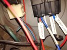
The switched power (Pink/Black) wire goes to terminal 86 on the main relay and the large red wire (Straight Power) goes to terminal 30. Since the large red wire is an unprotected circuit the wire from terminal 87/87a on the main relay it will connect directly to the fuse box that will distribute power to all the devices. Terminal 85 on the main relay goes to ground.
The B+ wire (Brown) from the fuel pump fuse goes to terminals 86 and 30 on the fuel pump relay. I soldered 2 wires onto the existing Brown wire and connected one to terminal 86 and the other to 30. It supplies power to the relay winding and the fuel pump once MS grounds the relay turning it on. The wire to the double relay that goes to the fuel pump can be connected directly to terminal 87 on the fuel pump relay. Since the circuit going to terminal 30 comes from the fuel pump fuse no additional protection is need. Terminal 85 connects to pin 8 (purple) of the mS harness.
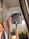
I ran the power from terminal 87 of the main relay to a Blue Sea Systems 5025 6 position fuse panel with a ground bus. The Blue Sea Systems fuse panels are the nicest I could find and are much better than anything the auto parts stores sell. These can be found at marine supply store. I got mine from West Marine.
Now that the main Relays were completed it was onto engine compartment items.
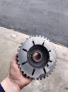
Crank Trigger Wheel:
This was purchased from DIYAutoTune. We machined down the center and welded it onto an existing Crank wheel. For timings sake, we did set the motor to TDC and then properly adjusted the missing tooth accordingly before welding into place. Painted black for aesthetics and made a bracket for the CPS, using feeler gauges to properly space out (0.030-0.060").


The Ford EDIS system took the most time in terms of wiring, I took extra care in shielding as well. Wiring for the EDIS is pretty straight forward using the below diagram.

See below for Firing Pattern as it's not the most clear on certain references.

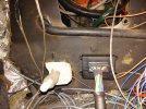
I mounted the ignition here with a custom (albeit amateur) bracket. Tucked the EDIS where the original ignition module was, alongside the capacitor.

Fuel Rail + Injector Bungs:


Fuel Pump:
Pretty straight forward here, totally overkill on what I used but I wanted to have visual as well as adjustment. Used AN fittings where I could and an inline filter.

Had to build a custom hard engine mount with a space for the fuel lines.

Oil Feed/Return:
Don't have any good pictures of the feed right now, but here is where we placed the return into the pan. We used a sandwich plate between the oil filter/block to get oil feed. This required a smaller filter (**This is a reminder to post the part number for that filter**)

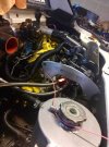
Turbo/Exhaust Manifold:

Mocking up the exhaust manifold/turbo. We did have to hammer down some spots to fit the intake manifold/trumpets.

Intake/Charge/BOV/Wastegate
Decently straight forward here


MAP Sensor located to the right of the plenum in picture above.

Notice the IAT welded here above.
Calling it a night, but will update more later. I want to add pictures of the intercooler (mounted in the rear valence) and exhaust (coming out of rear engine lid) at some point. I also purchased those eBay coolant pipes and took pictures to share fitment with y'all, overall very happy with them.
The first part of this introduction will be regarding the MicroSquirt wiring, the second being custom parts we built for the turbo. Big shoutout to @Matthew for his MegaSquirt write-up that assisted me along the way. (https://xwebforums.com/forum/index.php?threads/mega-squirt-project-details.13026/) Also my brother Ian, who I couldn't of done this without.
Parts List:
MicroSquirt: $388
Exhaust Manifold: Ali Express (LOL!) Found one that fit the Uno Turbo with slight modifications. Couldn't find factory Uno Turbo manifold at the time.
Fusable Double Relays: https://www.amazon.com/gp/product/B07PK7F1MC/ref=ppx_yo_dt_b_asin_title_o08_s00?ie=UTF8&psc=1 ($11)
Fuse Panel: https://www.amazon.com/gp/product/B000K2MBPA/ref=ppx_yo_dt_b_asin_title_o08_s00?ie=UTF8&psc=1 ($31)
36-1 Tooth Wheel for Crank: https://www.diyautotune.com/product/6-3-4-36-1-trigger-wheel/ ($30)
Crankshaft Position Sensor: https://www.amazon.com/gp/product/B01AIYMCU8/ref=ppx_yo_dt_b_asin_title_o01_s00?ie=UTF8&psc=1 ($17)
Crankshaft Position Sensor Pigtail: https://www.amazon.com/gp/product/B07DVNR2J6/ref=ppx_yo_dt_b_asin_title_o00_s00?ie=UTF8&psc=1 ($14)
Air Intake Temperature Sensor w/ Pigtail: https://www.amazon.com/gp/product/B07TD8FFVK/ref=ppx_yo_dt_b_asin_title_o02_s01?ie=UTF8&psc=1 ($17)
MAP Sensor: https://www.ebay.com/itm/381190256311 ($43)
Ford EDIS-4: Found used on eBay, paid ($40)
EDIS-4 Accel 140018 Coil: https://www.amazon.com/gp/product/B001OZW8PK/ref=ppx_yo_dt_b_asin_title_o03_s00?ie=UTF8&psc=1 ($83)
EDIS-Pigtail: https://www.ebay.com/itm/174291462121 ($17)
Spark Plug Wires: Local AutoZone/Advanced Auto, asked for a set from a 1994 Ford Escort.
Capacitor for EDIS: https://www.amazon.com/gp/product/B01MU8TMKX/ref=ppx_yo_dt_b_asin_title_o00_s00?ie=UTF8&psc=1 ($13)
Crank Position Sensor: https://www.amazon.com/gp/product/B01AIYMCU8/ref=ppx_yo_dt_b_asin_title_o01_s00?ie=UTF8&psc=1 ($17)
Solder & Seal Wire Connectors: https://www.amazon.com/gp/product/B07HCNTZ2Z/ref=ppx_yo_dt_b_asin_title_o02_s00?ie=UTF8&psc=1 ($12)
Assorted Heat Shrink Wire Connectors: https://www.amazon.com/gp/product/B087QTK1Y2/ref=ppx_yo_dt_b_asin_title_o02_s01?ie=UTF8&psc=1 ($19)
Crimping Tool: https://www.amazon.com/gp/product/B07WMB61J5/ref=ppx_yo_dt_b_asin_title_o02_s00?ie=UTF8&psc=1 ($27)
Wire Shielding: https://www.amazon.com/gp/product/B003HGHR3C/ref=ppx_yo_dt_b_asin_title_o02_s01?ie=UTF8&psc=1 ($68)
Friction Tape: https://www.amazon.com/gp/product/B0000CBIAT/ref=ppx_yo_dt_b_asin_title_o08_s00?ie=UTF8&psc=1 ($6)
Fuel Pump: 355 Walbro Inline ($300, this was a gift from my brother. . . . so free.99 for me and way overkill for this build)
Coolant Temp: Factory
Wideband: AEM
Oil Pressure: Mechanical Gauge fitted onto factory low oil pressure sensor
Fuel Pressure Regulator: https://www.amazon.com/Universal-Adjustable-Aluminum-Pressure-Regulator/dp/B08MDNLR8F/ref=sr_1_4?crid=QXNT9XCW95Z0&dchild=1&keywords=fuel+pressure+regulator&qid=1629840313&s=automotive&sprefix=fuel+pressure+,automotive,183&sr=1-4 ($46)
Oil Catch Can: eBay
Tial BOV: eBay
Turbo: TD04 out of Saab (origins unknown)
Fuel Rail: https://www.ebay.com/itm/202872125579 ($20 for 2ft)
Fuel Injector Bungs: https://www.ebay.com/itm/202944215713 ($25)
TPS: Bosch, had one laying around and the P/N is worn off.
AN Fittings: Universal AN-6, probably spent around $100 or so in various fittings/hoses
MicroSquirt:
I opted for the MicroSquirt instead of the Mega for a couple of reasons, the main being budget. The MegaSquirt runs around $645 +$85 for the harness ($730). The MicroSquirt cost me $388 with an 8' harness. Half of the cost. The second reason was overall features I did/didn't need. Previous threads have brought up the point of high impedance vs low impedance injectors, the MicroSquirt supports "2 high impedance injector outputs – max peak current 4.5 amps". Our cars from factory use low-impedance, so using stock requires a resistor box (good write ups can be found for making this, but it does require sourcing parts and time to make). Since I planned on using high impedance Honda Accord Injectors (K242A4) this did not matter to me. Opted to use these injectors because 1) I had spares from other K20 builds 2) Can really fine tune pulse/cc 3) I wanted to give myself a headache making a custom fuel rail that would fit our intake manifold.
Step one was ripping out the original Bosch wiring harness, nothing too difficult there except I didn't want to cut it up so feeding through the firewall was fun. From there I removed the ECU and Double Relay. The MicroSquirt will be mounted in the original ECU position and a double relay will be replaced with 2 single relays. Once again, thank you @Matthew for the descriptive write up on the fuel pump and Main relays. The fuse panel will be located just above the double relay. The notes below will be similar to Matthew's with a couple of my personal notes.
Wiring for the 2 relays was as follows:
FROM original Fiat wiring:
Big Red - Straight Power
Pink/Black - Switched Power
Brown - Fuel Pump Fuse
Green - Fuel Pump Positive
Black/Purple - Fuel Pump Ground
The switched power (Pink/Black) wire goes to terminal 86 on the main relay and the large red wire (Straight Power) goes to terminal 30. Since the large red wire is an unprotected circuit the wire from terminal 87/87a on the main relay it will connect directly to the fuse box that will distribute power to all the devices. Terminal 85 on the main relay goes to ground.
The B+ wire (Brown) from the fuel pump fuse goes to terminals 86 and 30 on the fuel pump relay. I soldered 2 wires onto the existing Brown wire and connected one to terminal 86 and the other to 30. It supplies power to the relay winding and the fuel pump once MS grounds the relay turning it on. The wire to the double relay that goes to the fuel pump can be connected directly to terminal 87 on the fuel pump relay. Since the circuit going to terminal 30 comes from the fuel pump fuse no additional protection is need. Terminal 85 connects to pin 8 (purple) of the mS harness.
I ran the power from terminal 87 of the main relay to a Blue Sea Systems 5025 6 position fuse panel with a ground bus. The Blue Sea Systems fuse panels are the nicest I could find and are much better than anything the auto parts stores sell. These can be found at marine supply store. I got mine from West Marine.
Now that the main Relays were completed it was onto engine compartment items.
Crank Trigger Wheel:
This was purchased from DIYAutoTune. We machined down the center and welded it onto an existing Crank wheel. For timings sake, we did set the motor to TDC and then properly adjusted the missing tooth accordingly before welding into place. Painted black for aesthetics and made a bracket for the CPS, using feeler gauges to properly space out (0.030-0.060").
The Ford EDIS system took the most time in terms of wiring, I took extra care in shielding as well. Wiring for the EDIS is pretty straight forward using the below diagram.
- 4 cylinder (EDIS4):
- On a four cylinder engine, with a firing order of 1342, that means the coil should be connected so that 1&4 are on coil A (left side when connector is at bottom), and 2&3 are connected to coil B (right side). Other firing orders are connected differently. Basically, you connect #1 and the third cylinder in the firing order to coil A, and the second and fourth cylinders in the firing order to coil B.
- On EDIS4, coil A is connected to pin 10 of the EDIS module, coil B is connected to pin 12 of the EDIS module. If these are connected the wrong way around, the coils will fire in a different order, and the spark plug wires will need to be rearranged.
- In TunerStudioMS, set:
- Trigger offset = 0° (this will vary slightly, depending on the wheel/pickup configuration),
- Ignition Input Capture to ''Rising Edge'
- Cranking Trigger to 'Calculated',
- Coil Charging Scheme to 'EDIS',
- Spark Output to 'Going High (Inverted)'.
- Trigger Wheel Teeth to '0' (zero)
- Set the predictor algorithm option to 'last interval'.
DO NOT set the missing tooth settings to 36-1 - set the Trigger Wheel Teeth to zero - the EDIS module takes care of the 36-1 wheel - your MicroSquirt® controller sees it as a regular distributor.
See below for Firing Pattern as it's not the most clear on certain references.
I mounted the ignition here with a custom (albeit amateur) bracket. Tucked the EDIS where the original ignition module was, alongside the capacitor.
Fuel Rail + Injector Bungs:
Fuel Pump:
Pretty straight forward here, totally overkill on what I used but I wanted to have visual as well as adjustment. Used AN fittings where I could and an inline filter.
Had to build a custom hard engine mount with a space for the fuel lines.
Oil Feed/Return:
Don't have any good pictures of the feed right now, but here is where we placed the return into the pan. We used a sandwich plate between the oil filter/block to get oil feed. This required a smaller filter (**This is a reminder to post the part number for that filter**)
Turbo/Exhaust Manifold:
Mocking up the exhaust manifold/turbo. We did have to hammer down some spots to fit the intake manifold/trumpets.
Intake/Charge/BOV/Wastegate
Decently straight forward here
MAP Sensor located to the right of the plenum in picture above.
Notice the IAT welded here above.
Calling it a night, but will update more later. I want to add pictures of the intercooler (mounted in the rear valence) and exhaust (coming out of rear engine lid) at some point. I also purchased those eBay coolant pipes and took pictures to share fitment with y'all, overall very happy with them.
Attachments
Last edited:
")

