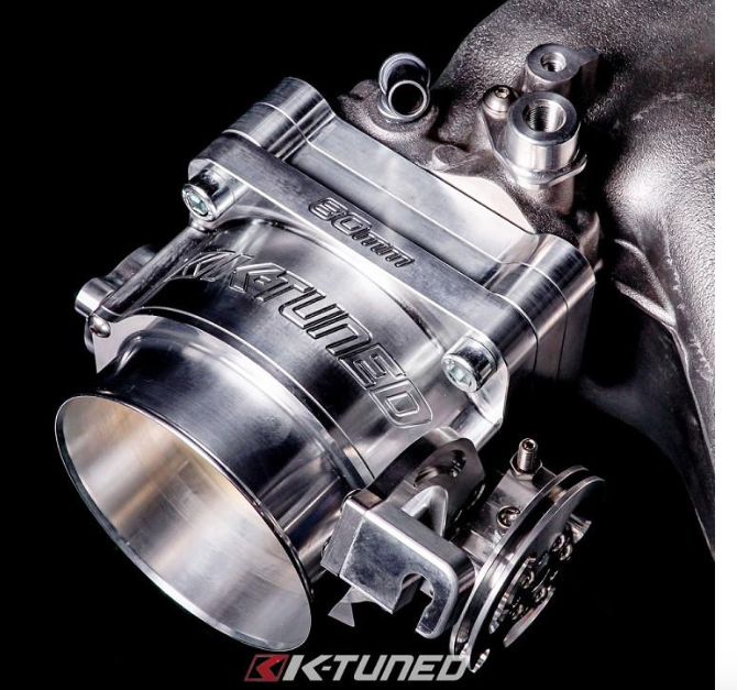
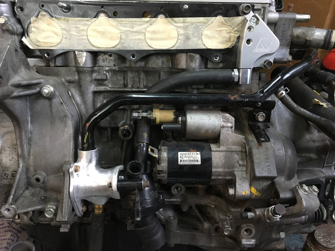
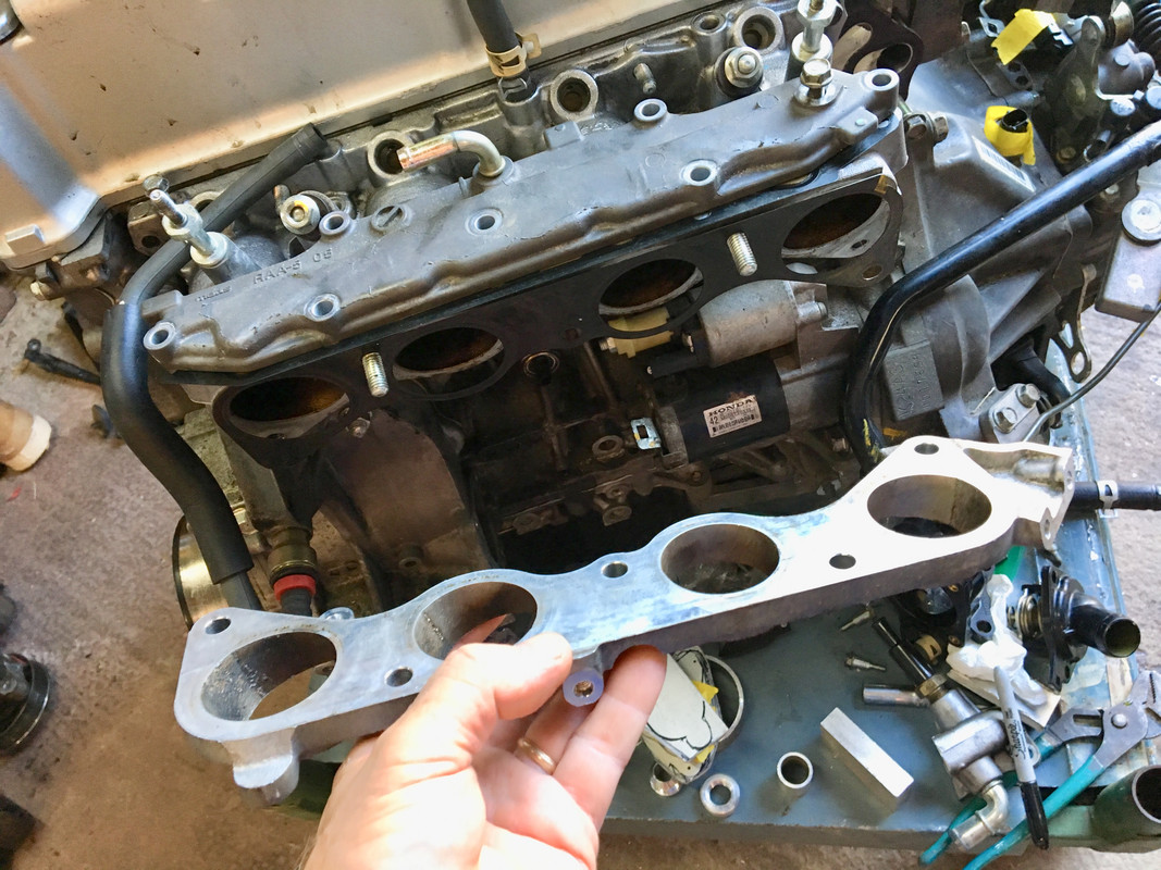
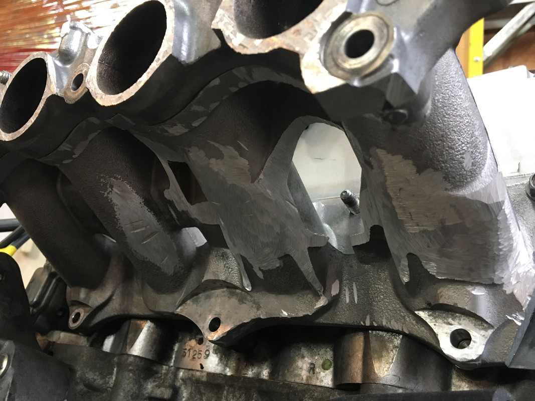
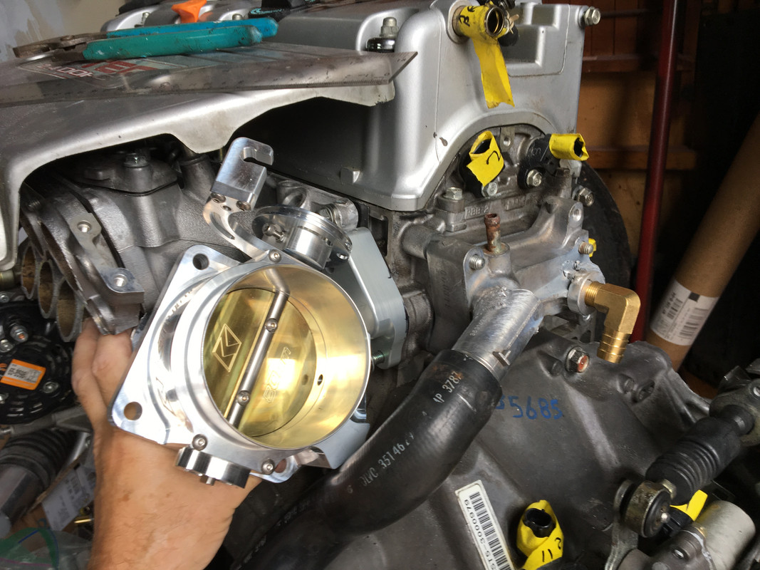
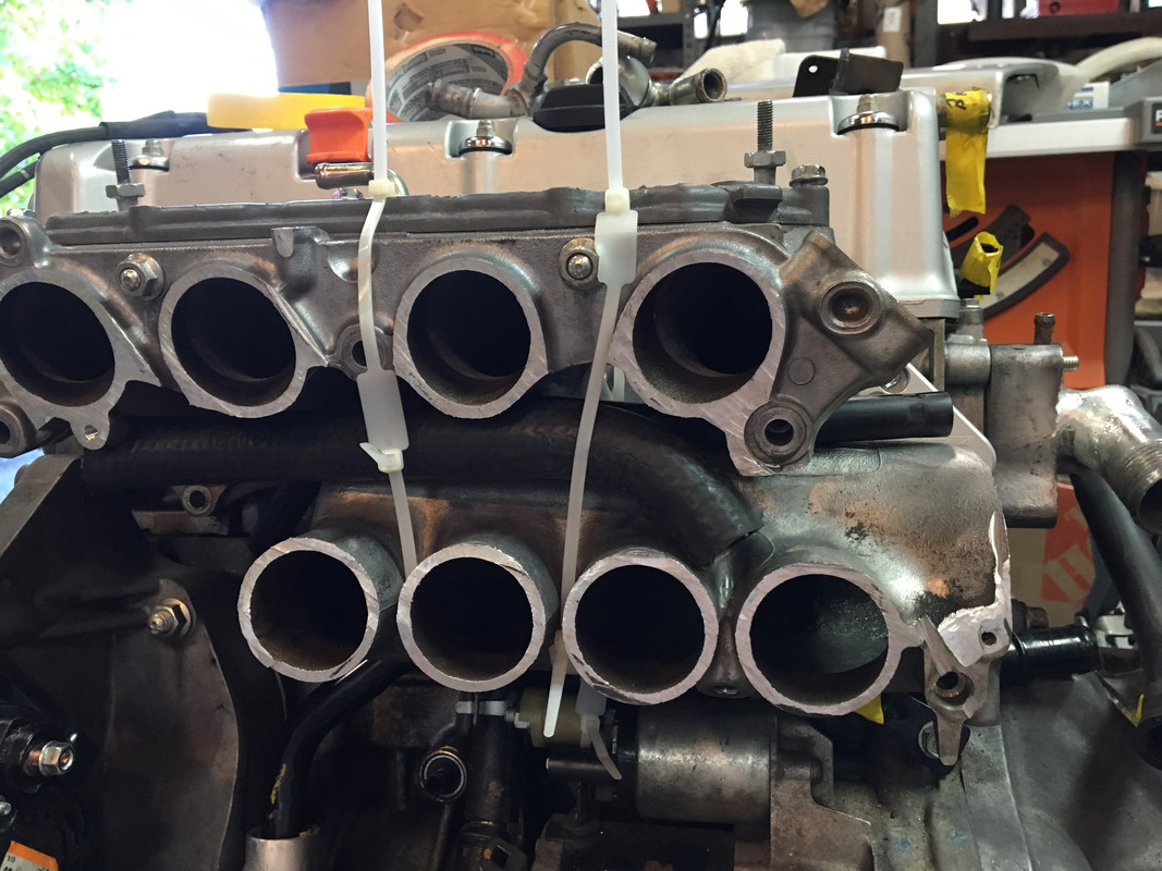
Nice casting.
")
Looks very good.
I know I am beating my own dead horse here, so feel free to ignore the following. After this I will keep it to myself as its not pertinent if its not something you want to do.
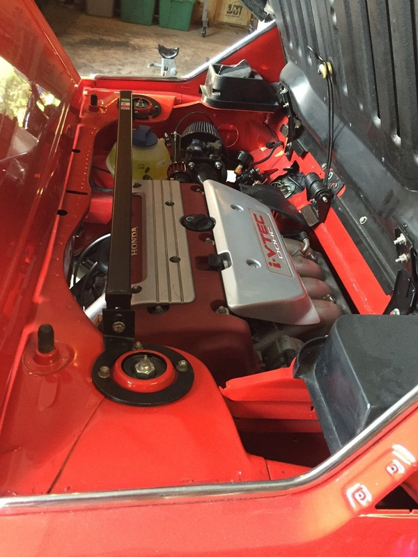
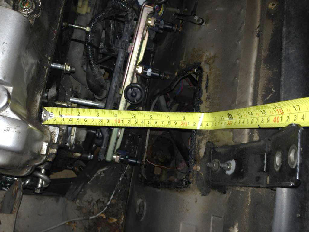
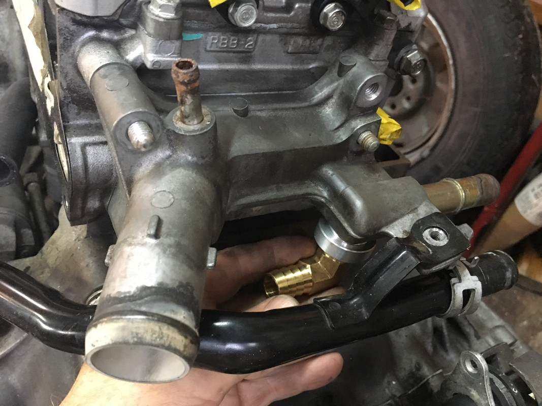
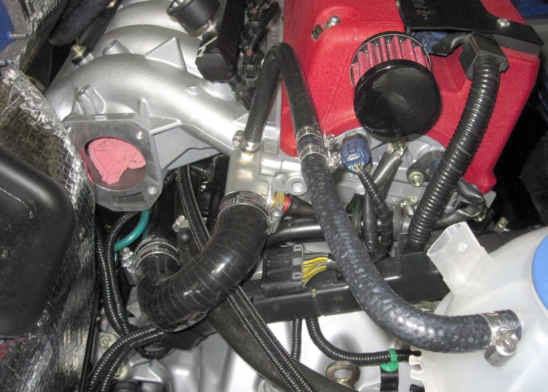
This engine, like most modern engines, was designed to be put under the lowest possible hood in a front drive car which can have plenty of room for hanging things in front of the engine. A proper length, downwardly curved manifold to clear that low hood then drives the accessories downward as well. As we all know, on an X there is a finite amount of room to the firewall and the structure of the car. Changing the manifold and going to an electric water pump would allow moving the alternator and AC compressor accessories upward, reducing the need to cut away so much of the structural tub around the lower area of the engine compartment. The alternator could be moved to the rear of the engine to make room for the compressor potentially though likely not needed.
I know that a spare tire is much less needed today, my beef isn’t (specifically) with cutting away that relatively non structural area, it is the lower tub of structure that is removed that I am more concerned with. One can add back the same amount of steel into the lower area but the reality is that the same amount of steel in a narrower cross section is not as strong as that same steel placed across a larger cross section. This is the base principal around the structural difference between a piece of bar stock versus a tube, a tube (with a thick wall) can have nearly the same strength as a bar of steel due to the fact that as the material gets closer to the center of the section the amount it contributes to stiffness is reduced very quickly to the point where it contributes nothing at the center. Additionally, inducing all manner of corners and sharp edges creates areas where stresses can contribute to cracking and folding under load. Load like a side impact or other impacts in addition to rhythmic loading from driving down the road and engine vibrations.
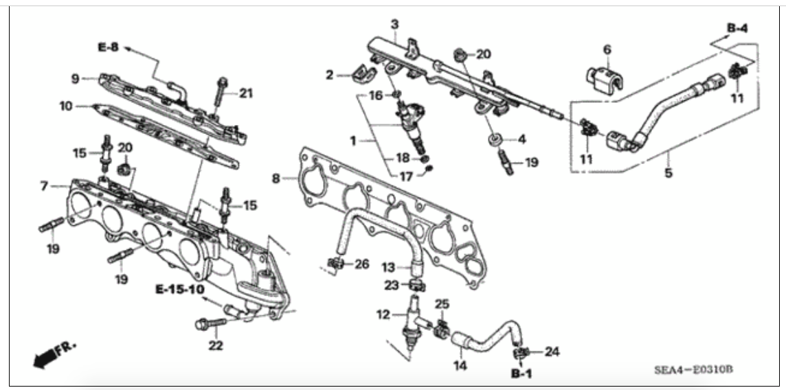
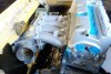
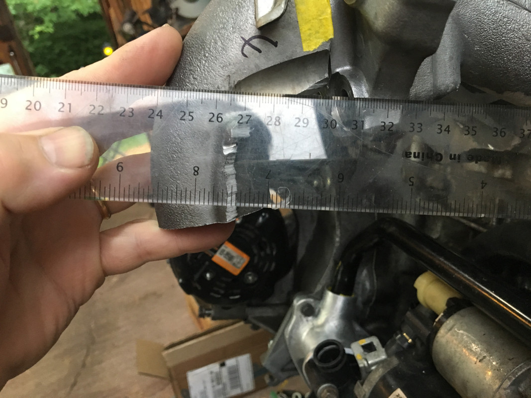
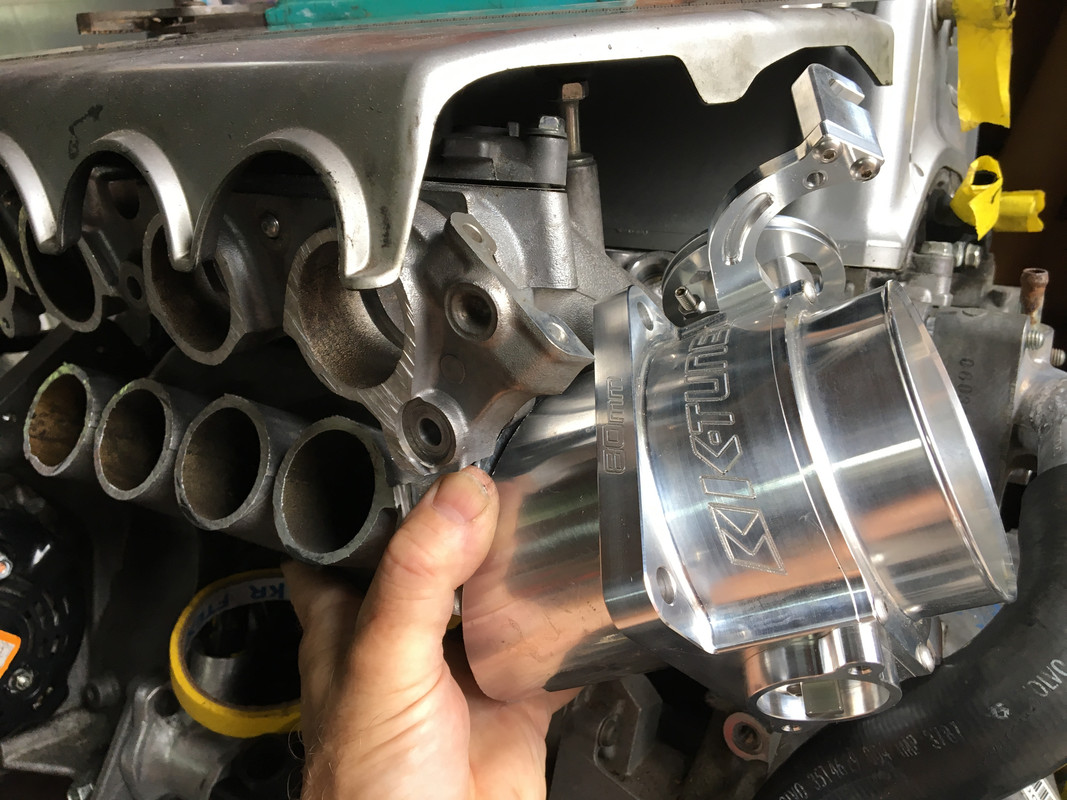
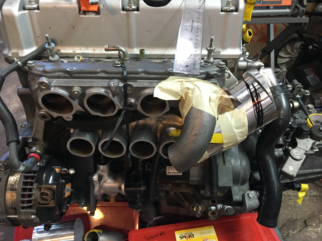
In looking at the cutaways of the K20 head (and Toyota 2ZZ head) the path to the valves in the head is effectively level or slightly pitched down to start then pitches down further to the valves in a fast arc. Coming from above in an upwardly facing arc isn’t much of a leap versus coming from a downwardly facing arc.
View attachment 15247 View attachment 15243
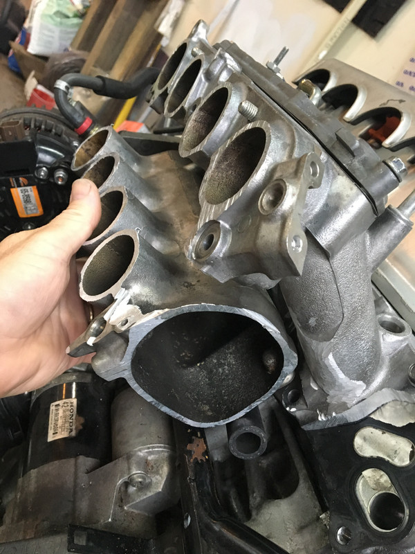
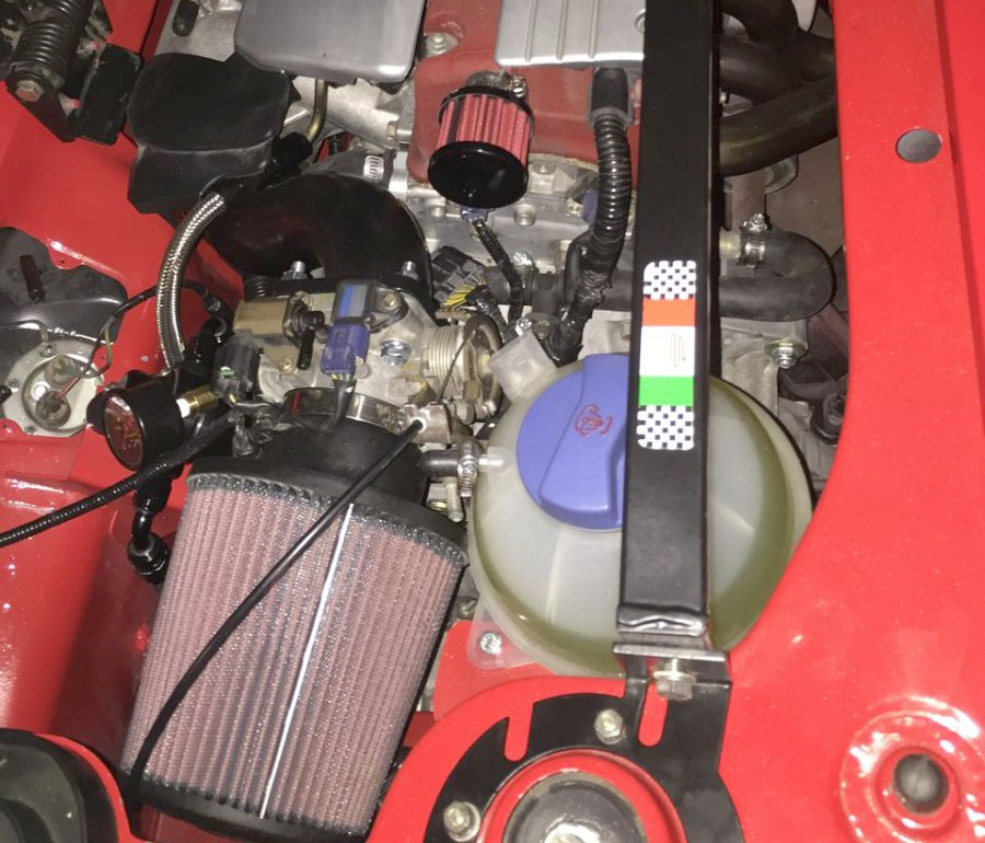
I know, different engine but handling a similar amount of air, the Toyota intakes do start with a flat arc in the intake and then start a fast curve down and around to meet the plenum which has an offset of the log to the extended curved transitions into the plenum log.
View attachment 15245 View attachment 15244
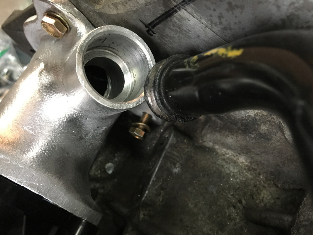
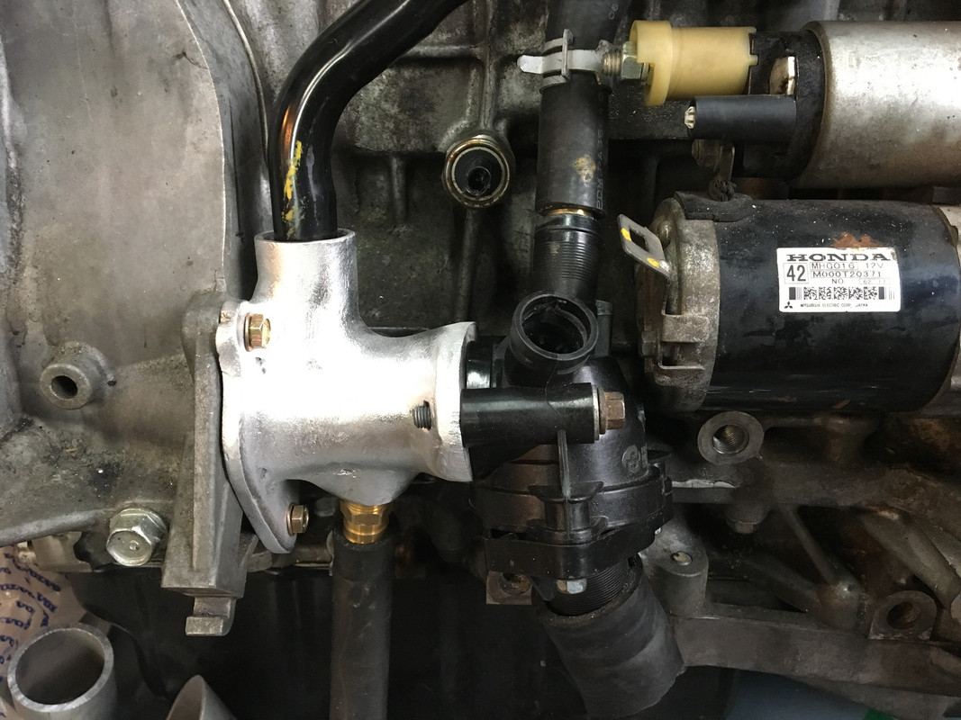
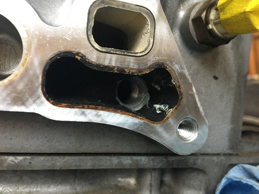
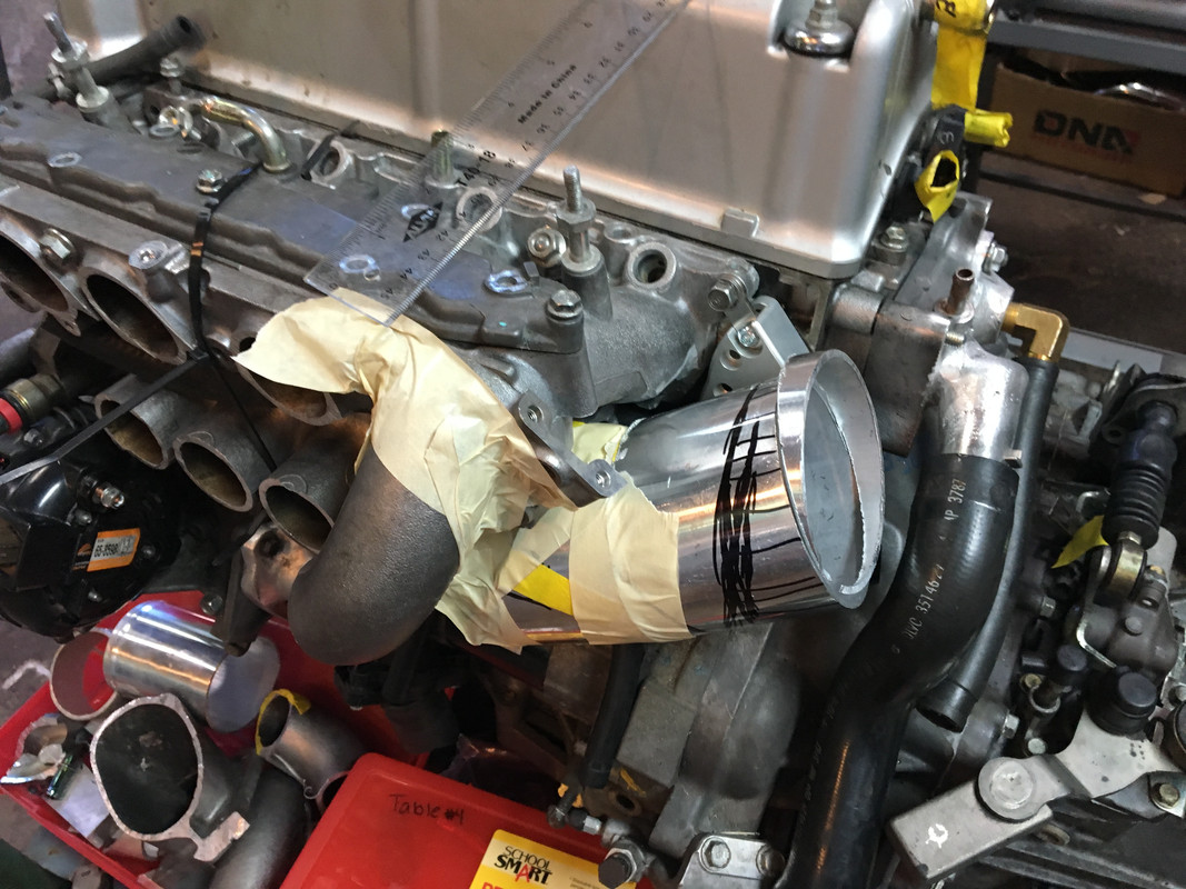
Following this logic one could start with an upward arc and then turn more quickly upward to place the intake plenum log where it will fit.
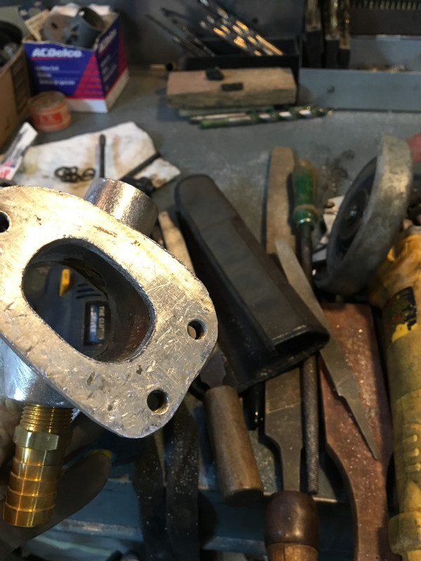
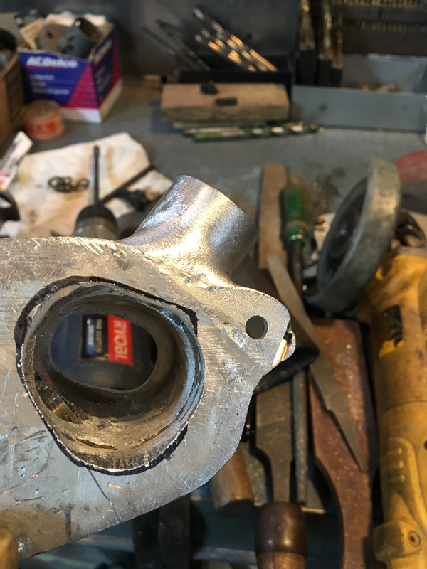
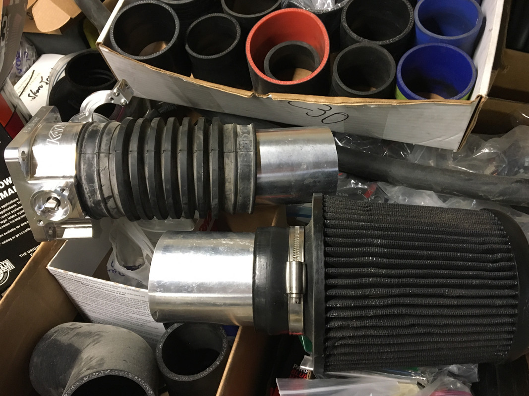
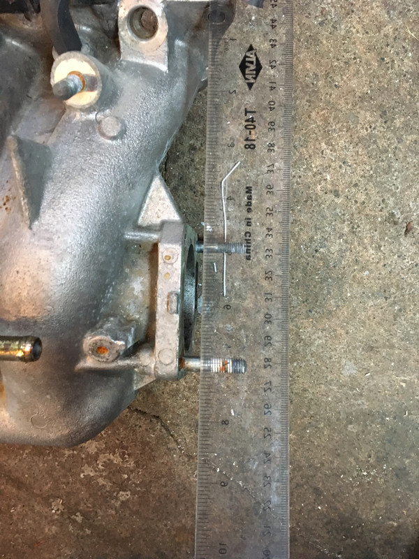
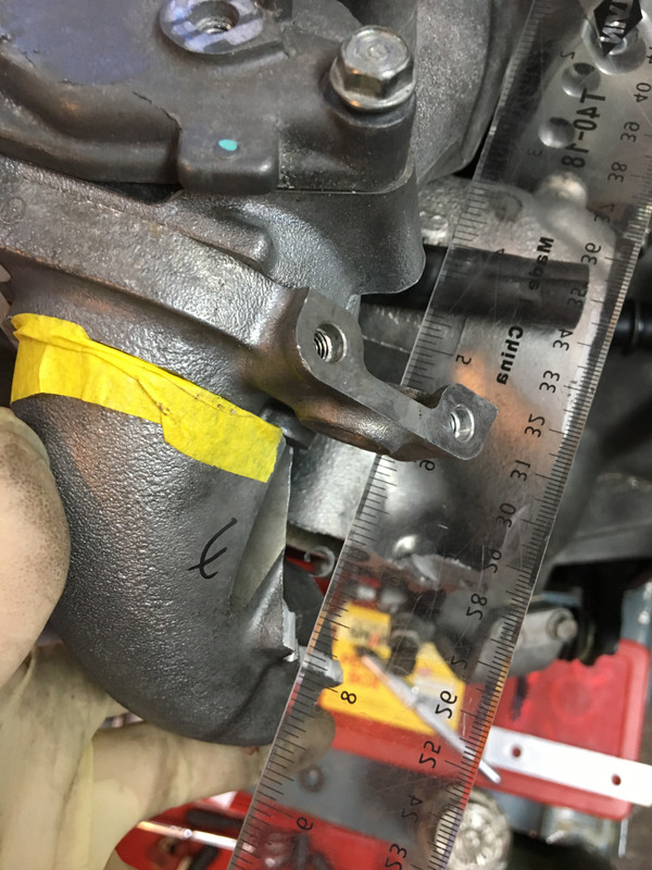
What could be done certainly can’t be resolved before putting the engine into the car. One could imagine cutting the existing castings apart and rewelding them or using a bolt on plenum to attach to fabricated SS or bent aluminum tubular runners going to a machined intake flange.
View attachment 15248View attachment 15249View attachment 15250View attachment 15242
https://xcessivemanufacturing.com/honda/k-series/honda-h-k-a2-bif.html
Given your handiwork it seems within the realm of possibility. Anyway, dead horse beating is done.
https://goo.gl/images/f7BFg2
Nice work as always, great to see.
Thanks
Karl