kmead
Old enough to know better
Bolts into thick concreteI don't understand! How does that not fall over?!

Bolts into thick concreteI don't understand! How does that not fall over?!
Just on the bottom? No top mounting?Bolts into thick concrete
There never is. It seems incredible that concrete can do that, but it do.Just on the bottom? No top mounting?
Regarding the front radius rod pivot mounts. I'm not clear which kit you are referring to, the urethane replacements?:I know that there is the kit to change this noted here( easy to replicate) but are there any other modifications of these bars to the body in a proper pivot?
I was referring to the alternate body mounts of the front sway bar Kit. But this is the next area to address.Regarding the front radius rod pivot mounts. I'm not clear which kit you are referring to, the urethane replacements?:
But there have been a few approaches to changing it to "real" pivot mounts. The more common one is to adapt heim joints onto the ends of the rods. Someone has pics of their setup but I don't have a copy. This is the same idea but on custom aftermarket race arms....see the heim joint end circled:
Ahhh, now I understand what you were referring to. I've never used a sway bar on any of my X's so I don't have any info on that, sorry. But I recall multiple approaches being discussed before.I was referring to the alternate body mounts of the front sway bar Kit. But this is the next area to address.
I have all the poly mounts but will be addressing the caster via the radius rod also.
That is an interesting control arm. Any info on it?
Might be a good idea to come up with a bracket that addresses both issues, sway bar mount and a reworked radius rod with a heim joint.
 autoricambi.us
My first thought with using a ball joint for the forward pivot mount is it might allow unwanted fore/aft (axial or linear) movement. Typically BJ's are used for loads that are more directed into the ball (e.g. on a front A-arm suspension) rather than across it. But after thinking about it that should not be the case. Especially with a BJ in good condition and well secured to the mount. However the design of the mount would need to include a solid tapered sleeve to accept the spindle on the BJ...not too difficult to achieve.An arrangement like the rear toe control rods would be nice using tie rod ends at the leading front end with the existing bolted mount at the factory lower arm tot he strut.
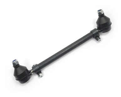
Perhaps the 124 tie rods with their tubular adjusters with clamps. Cut and thread the existing radius arm so you can just turn the tube just like the rear arm adjustment.
Complete Tie Rod Assembly
su4-468 FIAT 124 spider ROD STEERING SUSPENSION TIE TIEROD SLEEVE 4218164 4218233 4104085
I was thinking a standard busing style at the front of the radius rod and the stock mount at the control arm. this style ish.An arrangement like the rear toe control rods would be nice using tie rod ends at the leading front end with the existing bolted mount at the factory lower arm tot he strut.
Perhaps the 124 tie rods with their tubular adjusters with clamps. Cut and thread the existing radius arm so you can just turn the tube just like the rear arm adjustment.
Complete Tie Rod Assembly
su4-468 FIAT 124 spider ROD STEERING SUSPENSION TIE TIEROD SLEEVE 4218164 4218233 4104085

I haven't thought this through to know if it would work, but I wonder if a sway bar could replace the radius (trailing) arms completely....assuming the sway bar was designed to do so. The mounting points could be the ones used by the original trailing arms at both ends. Something along this idea:Well now I have a better idea how to make one mount for the radius rod and the body mount for the sway bar. The body where the other kit mounts the new sway bar blocks is way to uneven and thin. I always believe that what ever mounts to the sheet metal has to have a block bigger than the block on the other side to sandwich and keep the metal from being sheared. A common mount using the three radius arm threaded inserts would be far better.
View attachment 73615
Looks like the caster adjustment might need to be on the forward end in order to use a one piece sway bar that will handle the torque load.I haven't thought this through to know if it would work, but I wonder if a sway bar could replace the radius (trailing) arms completely....assuming the sway bar was designed to do so. The mounting points could be the ones used by the original trailing arms at both ends. Something along this idea:
View attachment 73616
Good point. I imagine that could be done but the adjustment portion would need to be strong enough for the loads as well.Looks like the caster adjustment might need to be on the forward end in order to use a one piece sway bar that will handle the torque load.
Just saw that. I had a little trouble trying to figure out what it all looked like from the photos. Evidently a different style mount than the Addco type that is common due to it's simple implementation. I think my 7/8" Addco bar may have been the first mod I did to the car. Really killed the body roll and oversteer. There are some that don't think the Addco mounting is elegant enough because it does not tie directly to the body but it worked good enough to solve my problem.Just saw another thread on this topic:
Weird Front anti sway bar mounts
I just got my car a few months ago, been going through a list of stuff to look at. As I was check the front frame and suspension mounts. I fount these L steel brackets welded to the chassis for a sway bar mount. Should I just keep it. Doesn't cause any issues while driving..xwebforums.com
My Addco attaches to the trailing arms as a substitute for tying to the body. The sway bar ends connect to the control arms. If a bar is not tied to the body somehow, I'm not sure it would develop much force by only working against the opposite control arm unless they were rigidly tied together to prevent movement in all planes. Maybe that is how the ones in your photos work but I can't tell without seeing how the ends are attached to the control arms.Wasn't there one example where the sway bar was simply anchored solidly to the two trailing arms, and no other attachments? That is how many of the rear bars are mounted for other vehicles.
View attachment 73621View attachment 73622
Ones like in the sample pics I posted are connected solidly to the suspension trailing arms in more than one point on either side. So the legs of the sway bar are essentially an extension of the trailing arms. With that arrangement the sway bar does not attach to the body/chassis at all. Instead it is like a torsion bar spring in between to two suspension training arms (which is essentially what all sway bars are). Just a different design. I think it works better on a solid rear axle system than a independant one, but I seem to recall someone had that sort of arrangement on the front sway bar for their X1/9.My Addco attaches to the trailing arms as a substitute for tying to the body. The sway bar ends connect to the control arms. If a bar is not tied to the body somehow, I'm not sure it would develop much force by only working against the opposite control arm unless they were rigidly tied together to prevent movement in all planes. Maybe that is how the ones in your photos work but I can't tell without seeing how the ends are attached to the control arms.