Performing Honda K24a3/AST5 6spd Conversion

Hussein, that is what swaps are about. The kind of character that sticks with the mission to the resolution. That is why the drive will always put a smile on your face, because it is your build that no manufacture has managed to build. Revel in the moment, it is well deserved. Not everyone can do this kind of work, that too is rare. Looking forward to some longer videos in the future.

Just wanted to share something with you when working on AC systems... a trouble shooting tool kit that I purchased from China for $150 USD. With this kit you can prove any hose any fitting any component in the system as a whole or in part. It allows you to isolate any of the above for testing. I found that it is worth the money spent.

IMG_1716.JPG


TonyK.

Grimsby Ontario Canada.
 
Rewired the SCS signal to the OBDII #9 position, where it belongs. While I was in there, I put AC tape on the low side line. Made sure the heater line was no longer seeping before I put the cover panel back in.

IMG-20200327-142730.jpg


Took the left axle out, to figure out the weeping seal. Inner CV has to be levered out, to release the retaining circlip. Fortunately there is much room to get a long pry bar in there from the rearward edge, using the fill plug as a lever point so the casing isn't damaged. Note: Fluid did not need to be drained - when car is jacked up, the fluid is below the axle entry in the carrier casing

IMG-20200327-163133.jpg


The Febest inner CV - (44310-TA0-A60) - has no surface issues, it does feel like there is more play with it inserted in the diff splines than one would expect, but I checked it in the factory diff I removed, and it is the same for both MFactory & stock diff.

IMG-20200327-163620.jpg


This is the seal that was weeping. No evidence of li[p damage, and I didn't install it too deep in the casing, which was one possibility I had considered, as that would move the inner lip to the outer edge of seal seat.

IMG-20200327-163715.jpg


seal-crop.jpg


new & removed side by side

IMG-20200327-163914.jpg


What I found was that the seal I had installed on the left is actually a right side seal - based on the numbers on it, it's the same manufacturer as the SKF (15888) I bought as a replacement for the right side (Honda # 91206-PHR-003). What doesn't make sense is the dimensions given for the right side are 35x58x8 - but what I removed is 40x56x8, which are the dimensions of the left seal (Honda 91206-PL3-B01). If it were 58mm it wouldn't fit in the left side of the casing.

The exception is that the outward inner lip is about a mm larger than the innermost lip (compared to the Honda where both inner & outer lips are the same ID), so maybe that was why it leaked.

Used an old (Fiat hub?) bearing to install the new seal (shown with old seal here)

IMG-20200327-170613.jpg


IMG-20200327-170606.jpg


New seal in place

IMG-20200327-164852.jpg


axle back in, outer CV bolts retorqued to 31ft/lbs.

IMG-20200327-170007.jpg
 
Last edited:
Glad you found a solution to the erratic idle.
Sorry if my search for the TPS problem might have caused the vacuum hose problem.

However, you know that I'm not giving up on the TPS. Having all of this info available means that there is ALWAYS something that you can make better or just fix.
Looking at your data from above I see that the "65%" is still in the ECU. What's confusing is that in both the 2nd and 3rd gear pulls the throttle % is right at 65% (64 and 66%). The RPM is basically the same at that point in both gears. The AFR is 14.4 in 2nd and 10.4 in 3rd. I can't see what happens before or after these instants, but it would be interesting to see why there is that big a difference in the AFR's under what looks like the same conditions.

Anyway, congrats on finding the idle problem.

Can't really go by the screenshots, as the duty cycle & AFR changes in a split-second. Without watching the playback it's ahrd to see. I can say the load in second is much less that third, and pressing the pedal harder puts it in the WOT mode, which seems to go pig-rich in 3rd or higher.

I have 80% max throttle, which apparently is the max reading according to others on K-Tuner. The voltage is correct for WOT (4.7v), so I'm not going to worry about that aspect at the moment, I'll take it up with the tuner when I get to that point.
 
Hussein, that is what swaps are about. The kind of character that sticks with the mission to the resolution. That is why the drive will always put a smile on your face, because it is your build that no manufacture has managed to build. Revel in the moment, it is well deserved. Not everyone can do this kind of work, that too is rare. Looking forward to some longer videos in the future.

Just wanted to share something with you when working on AC systems... a trouble shooting tool kit that I purchased from China for $150 USD. With this kit you can prove any hose any fitting any component in the system as a whole or in part. It allows you to isolate any of the above for testing. I found that it is worth the money spent.

View attachment 30271


TonyK.

Grimsby Ontario Canada.

Hey Tony, thanks for the reminder :D - I did take it out this afternoon - sun was out, it was about 70ºF, and there was a light breeze. Perfect weather for driving around, and it did put plenty of smiles on my face, it's a pleasure to drive now with the drivability issues corrected. :)

I recall seeing the pic of that kit in another thread - it looks to be worth every penny. Can you share the source - searching for test hose & fitting kits doesn't return any meaningful results.
 
Put a little over 300 miles on it now. Seemed like all the fluid leaks were resolved, then I had a couple drops of something on the tarp I'm parking it on. Turns out, the #8 AC hard lines I made were all seeping at a spot on the welds I made.

IMG-20200407-145358.jpg


IMG-20200407-152145.jpg


Anyway, I decided to make a single line using #8 reduced barrier hose & fittings. I was able to make a single run from the underbody #8 to the compressor, so only 2 unions vs. 6. Had to crimp the elbows in place, so that hose is not removable intact. Shouldn't ever be a reason to do so, it's not in the way.

IMG-20200407-160223.jpg


IMG-20200407-160236.jpg


IMG-20200407-160305.jpg


To keep it from potentially flopping on to the idler pulley over time
IMG-20200407-171159.jpg


Installed the accumulator-mounted AC cycling switch instead of the Fiat switch

IMG-20200323-160544.jpg
 
Last edited:
PWM controller

IMG-20200107-180941.jpg

So, I got this pwm controller off Amazon. It came with these directions, which I really didn't look at closely at the time. I have no clue how to interpret WTF they are saying in terms of adjustment, and it doesn't give the preset value it was delivered with anywhere. Can anyone here comprehend and translate for me :D ? I have posted questions on the website also.

Icstation 12V 4 Wire PWM.jpg
 
In my experience, once you figure out to how to operate it, the instructions will be clear. I have no idea what the instructions mean. I suspect it will take an oscilloscope (or digital equivalent) to figure it out.

Paul
 
So, I got this pwm controller off Amazon. It came with these directions, which I really didn't look at closely at the time. I have no clue how to interpret WTF they are saying in terms of adjustment, and it doesn't give the preset value it was delivered with anywhere. Can anyone here comprehend and translate for me :D ? I have posted questions on the website also.

View attachment 30702
Got a link and info as to why you bought it?
 
Got a link and info as to why you bought it?

Its to control the ECU fan

amazon link

I need to figure out how to make it come on somewhere around 90ºF, and ramp up over 100ºF I reckon.


355 miles on it now

IMG-20200409-164019.jpg


Had the bloody P1009 code come back yesterday, even just driving sedately. Since it had been fine since I revised the software, I figure it's likely the cheap VTC solenoid I bought off Amazon. I put the original one back in, and it's fine so far. Se how that goes.
 
Last edited:
So, I got this pwm controller off Amazon. It came with these directions, which I really didn't look at closely at the time. I have no clue how to interpret WTF they are saying in terms of adjustment, and it doesn't give the preset value it was delivered with anywhere. Can anyone here comprehend and translate for me :D ? I have posted questions on the website also.

View attachment 30702
Hussein, could you show a picture of the controller push button/s and Led's. I had a similar one for Bob Martin's car to run the intercooler fans, but to be honest I gave up for one that had on/off settings with DIP switches. The issue with this controller being PWM, Td ( Time delay) Then TU for differential temperature change, well it does so much it gets complicated in short order. It also will not save if the parameters are not instructed to change, but the mode automatically saves the changes. Who ever designed this works with this all of the time. What I can see happening is by the time you figure out where you are with the 3 LED's it will either save your entry or delete it because you are not fast enough in inputting your instructions. You may have to lay out a sheet of what mode you are in, what lights should be lit and how to save instructions.

TonyK.

Grimsby Ontario Canada.

This is it:

IMG-20200107-180941.jpg


Do you have a link to the style you used? I have no hope of figuring this one out. I tried looking for the sequence of lights & it's just way too confusing.

EDIT : Found this one - please let me know if that is essentially what you used

ZFC39

Screen Shot 2020-04-10 at 8.35.07 AM.png


explained by a end user (can't understand the 'official' directions as usual):

Screen Shot 2020-04-10 at 8.28.51 AM.png
 
Last edited:
Hussein, look at this one. It is an on/off unit not PWM. I tried looking for the spare that I purchased but could not find it. I know it is around here somewhere.

TonyK.

Grimsby Ontario Canada.

Hey Tony - thanks for the link - the fan I have runs via PWM, so I need a controller for that.

I got the one I linked, so just have to install & test the settings.

I reflashed the tune with adjusted base idle raised to 1050 - the idle is 1025-1075, so when it was at 1000, it keep trying to reach the target without success. Been OK the past few days. I may just raise it to 1075 & leave it there. It's not possible to get factory idle anyway. The intermittent P1009 VTC code hasn't come back - it could even be the connector - I have plugged & unplugged it & had the code go away, so I may need to re-pin it (once I figure out the terminals).

I bought a spare expansion cap & removed the (22lb) pressure valve & made a modifed spring seat that vents around 4lbs, more than enough for the Evans Waterlass, which doesn't need any system pressure. With that, the worst of the coolant smoke on startup is gone, there is still a problem to be sure, howver I don't feel like removing the head & replacing the gasket at this point. Can't see it being anything else at this point.
 
With all the other drama - I forgot to post here yesterday - I need to lay this out so I don't forget.

I finally resolved the drivability problems I had been having that made the car less than pleasant to drive unless under heavy throttle. Part throttle (partial tip-in, maybe 2-5% open) can result in engine surge and wild AFR (lean) sweep. Feels like driving with someone who doesn't know how to operate a clutch, if you know what I mean.

I've been back & forth in the K-Tuner software forum - not much help there at all, so I posted my problem on the K20a.org forum, and got a few helpful suggestions as to where to look when logging for meaningful interpretation of the data flow. So, the bottom line there was that I needed to get some fresh datalogs, from a cold start through warmup. They offered to review the logs & help me figure out where to go from there.

I drove the car to work yesterday morning - 15-20min drive, mix of local & highway driving so perfect for a comprehensive driving log. It did pour with rain in the north of the county where my school is, so I was able to check that I am leak free around the doors and targa :)

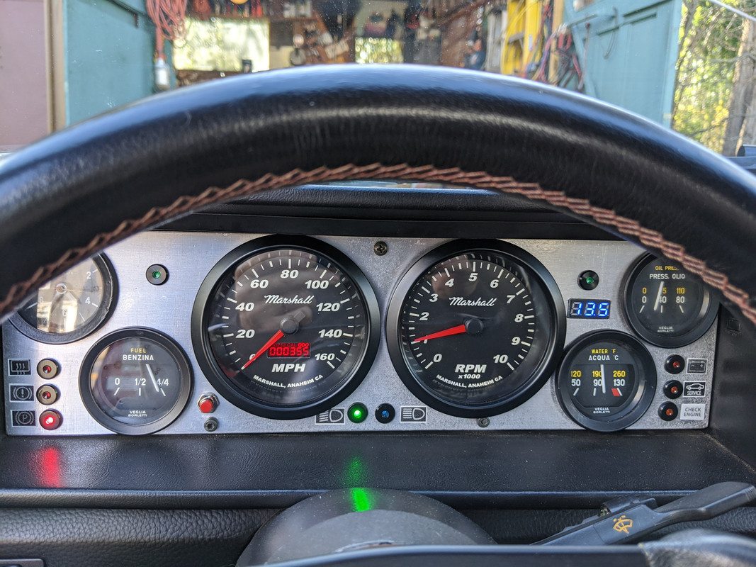
What I noticed while driving (I glanced at the main screen to make sure the recording was staying active) that displayed throttle % was not matching my pedal position in that low tip-in range - it seemed to be lagging behind the actual. Anyway, I completed the logs, did what I needed to do at school, and went home to get on with the iLearning school day. As an aside, when I left school I noted that the battery voltage was low & cranked a little slow. I realized the battery is probably 7 years old now.

After work, I went & bought a new Interstate M-24F in town, and I decided before I sent in the datalogs for review, I'd better check the TPS setting relative to butterfly opening/pedal position, so I hooked up the laptop & checked it from the pedal, and from the bobbin. In both cases there was a lag - in other words, the throttle plate was open several degrees before it registered. It seemed to me that that would explain most if not all the drivability issues. It was puzzling, as I had gone over the butterfly & TPS settings several times.

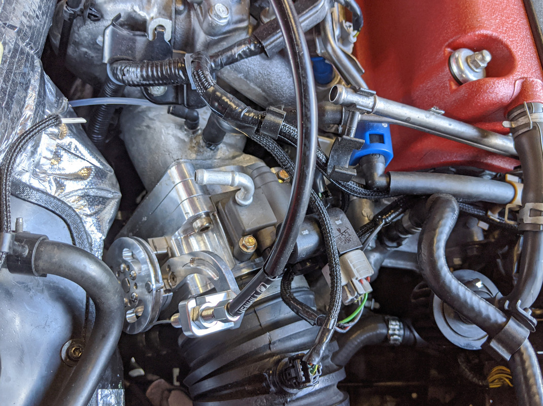
There is no way to get to the TPS without removing the TB

IMG-20200501-143610.jpg


IMG-20200501-143605.jpg


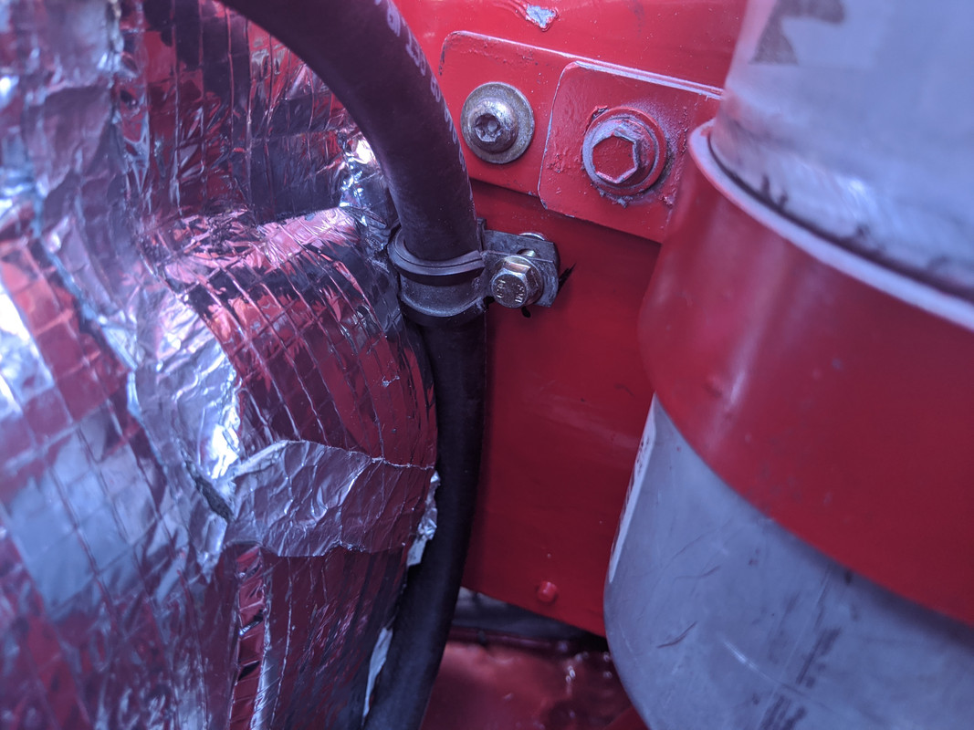
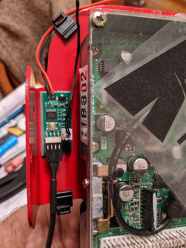
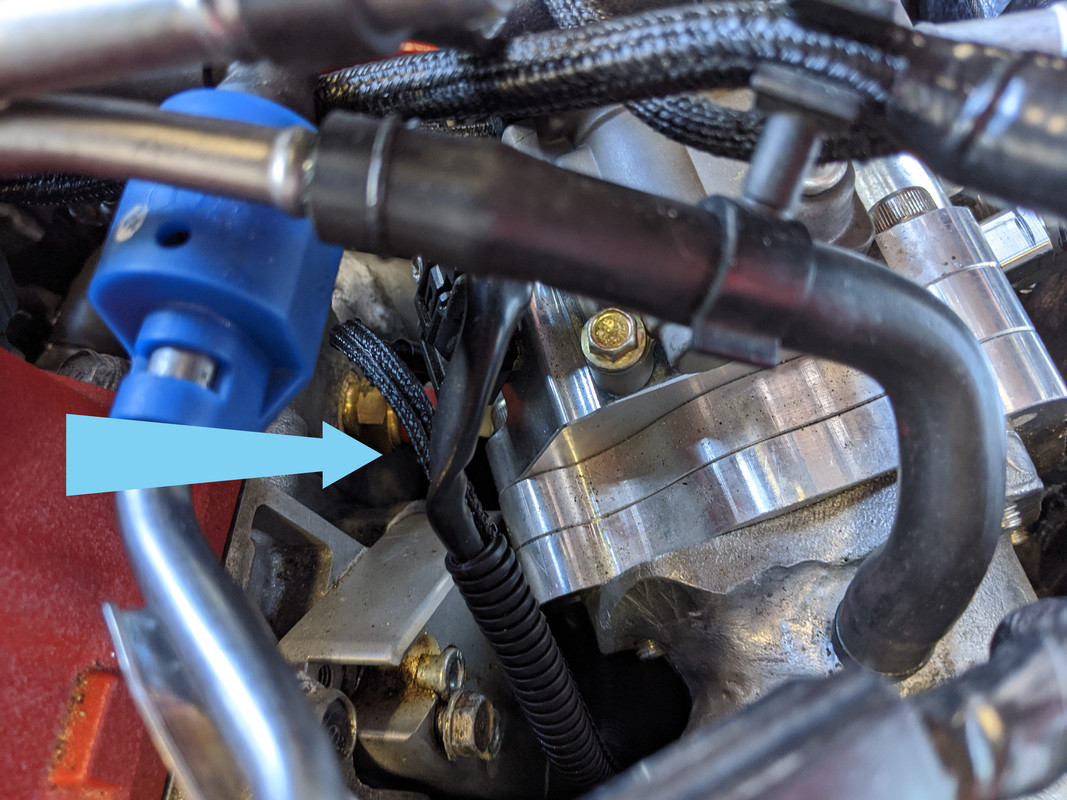
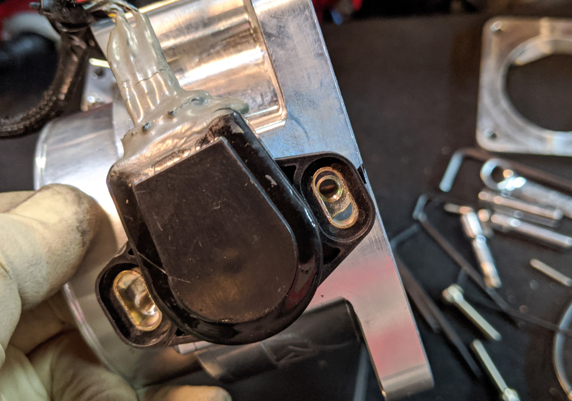
After removing the TB, I had to remove the TPS & K-Tuned adaptor plate & rework the plate mount again - as an addtional complication, the way K-Tuned mounted this (below) the TPS was not in the proper range. The new problem was that in the modified position, I had not allowed for a wide enough adjustment window, and it was all the way up against the stop. I had to dremel the slot to allow the mount plate to rotate another few degrees CCW, which then moved the TPS mount screws into the middle of the adjustment range. With that, I was able to center the TPS on the shaft, and get it adjusted so that the butterfly angle registered in the software immediately, with no lag or disconnect.

(Old pics, to illustrate TPS mounting)
IMG-20200122-171149.jpg


IMG-20200122-171335.jpg


Put it back together, double checked the butterfly repsonse from the bobbin & at the pedal, all good. I took it for a drive to check if that resolved the problem, which it certainly seemed to have done. Then I drove it off the road :(
 
Last edited:
Sounded really good right up until the last sentence.

These modern parts really are precision instruments compared to old fuel injection and carburetors.

Good sleuthing.
 
In both cases there was a lag - in other words, the throttle plate was open several degrees before it registered. It seemed to me that that would explain most if not all the drivability issues. It was puzzling, as I had gone over the butterfly & TPS settings several times.
It sounds like you resolved this problem and I know you have more pressing issues right now, but just wondering....was this a mechanical problem with how your TPS was mounted? I am not familiar with the K-Tuner software, but in Kpro, there is a place in the software where you can calibrate your TPS signal to reflect actual full closed and full open throttle. I recently changed my stock K20 TPS to one from K-Tuned, based on a recommendation from Jeff Evans in one of his video lessons. He said that the stock K20 TPS units fail pretty often in swapped cars because of the typical stiffness of the engine mounts. He said the B series TPS units are quite robust as well, so maybe that is what you are using. Anyway, it was a simple matter to swap in the new TPS and then calibrate it in the software.
 
Www
It sounds like you resolved this problem and I know you have more pressing issues right now, but just wondering....was this a mechanical problem with how your TPS was mounted? I am not familiar with the K-Tuner software, but in Kpro, there is a place in the software where you can calibrate your TPS signal to reflect actual full closed and full open throttle. I recently changed my stock K20 TPS to one from K-Tuned, based on a recommendation from Jeff Evans in one of his video lessons. He said that the stock K20 TPS units fail pretty often in swapped cars because of the typical stiffness of the engine mounts. He said the B series TPS units are quite robust as well, so maybe that is what you are using. Anyway, it was a simple matter to swap in the new TPS and then calibrate it in the software.

In K-Tuner, there is a TPS calibration window, where you can calibrate for 0%, or over 1% - the latter will make the system ignore the idle target settings. I have always been able to calibrate the base setting, the problem was once the throttle plate opened in small increments. The TPS is a generic Dorman-packaged item for K-series TB - I don't know if a B series style would fit the housing, or give the right signal.

I'm not sure how engine vibration would impact the TPS, he is saying the internal mechanism is compromised due to harsh vibrations typical when more rigid mounts are used?

I would have to say yes, it was due to the mounting - the issue appears to be due to the mod I had to make to the mount plate for the TPS - as my drilling new holes likely caused the mount plate to be eccentric relative to the shaft, which would bind the TPS mechanism & account for the delayed response when pressing in very small increments. When I redid the mount plate holes to move the TPS housing adjustment slots, I made sure to note the plate was properly centered on the shaft base - I have to assume it made a difference since the problem (% of throttle angle response) was remediated after that.
 
Back
Top