Selling the X & Bought an 75 Datsun 280Z

New lamp gaskets finally arrived, so I reinstalled my tail light panels back onto the tail lamps. I will need to source new ones DTR, they are so brittle, they keep cracking when I handle them. Also had to use 3M VHB tape to glue the panels the lamps, as most of the screw mount posts are so brittle they snapped & crumbled when I tried to reinstall them.

PXL_20231105_203052534-2.jpg


PXL_20231105_204556546.jpg

PXL_20231105_204549968.jpg

PXL_20231105_204538548-2.thumb.jpg.f016c3587edf684c1bf0067a18032b88.jpg


PXL_20231105_204735418.jpg

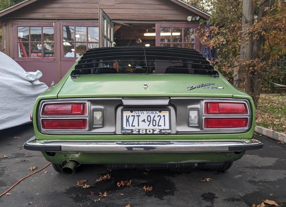
with those installed, I was able to put the rear panel back in. I added closed cell foam to give some more density
PXL_20231105_204811872.jpg


PXL_20231105_212036447.jpg


all back together - hopefully its quieter with the tail panel back in
PXL_20231105_212415752.jpg
 
Last edited:
Been out of town since Wednesday -

IMG_20231111_080640.jpg


before that, I had the heat soak issue even though the ambient temps were in the 40's-50's. I'm going to make a heat shield, however since I have to remove the rail again, I decided to get newer injectors & a billet rail, and just get rid of all those thin metal tube rails.

These came while I was away

ProtunerZ rail & injector seat adaptors, 19.4lb/hr Bosch injectors 0280155712 (GM, Saab application)

PXL_20231112_222440547.jpg

Fixed the annoying squeak from the console lid

PXL_20231107_202127209.jpg


new door cards came
PXL_20231106_181659294.jpg
 
Last edited:
Test fitting the ProtunerZ rail & adaptors, made a new section of fuel feed using 6AN braided hose, and a 6AN U-bend to feed the CSV

PXL_20231113_210536931.jpg

Adaptors came with SS Allen head screws, I don't like them. So, I used coated Sems screws

PXL_20231113_212452972.jpg

PXL_20231113_212456984.jpg

Bosch 0280155712 205cc
PXL_20231113_221520867.jpg

Added a support off the stock forward head mount point

PXL_20231113_221440312.jpg

Back together & running. I'm working on a heat shield template.

PXL_20231113_221437031.jpg
Just a few steps to Megasquirt.

Wow, quite a left turn at Albuquerque.
 
Car is running really well & starting well, with the HEI and the new injector & rail setup. Just a reminder that I also have the Volvo 3bar regulator, and Pot. setup on the ECT circuit, set about 900ohms richer than the factory value at any given temp. I used that to dial in 14.7 at warm idle.

Tried to get a pic with the WBO2 reading 14.7 cruising - you'll have to take my word for it
PXL_20231114_191325138.MP.jpg

One of the ORB-8 to 6AN adaptors that came with the rail wouldn't seal in the AN line fitting, I had gas seepage. Swapped it out for the other one they provided & it's all good
PXL_20231114_210342836.jpg

Working on the heat shield template
PXL_20231114_163535926.jpg

PXL_20231114_151250184.jpg

PXL_20231114_160732698.jpg
 
Last edited:
Just a few steps to Megasquirt.

Wow, quite a left turn at Albuquerque.
Lost track of whether I talked about the heat soaking issue on here - driving the car, then parking & restarting it after about 10-15min results in a nasty lean condition that takes a minute or more to level out. Don't know if it's the stock injectors or the thin tube rail that creates the conditions for this, however it is a known thing on the Z forums. It's going to be more than a year (maybe 2) before the conversion, so I want it good to go in any ambient temps.
 
Car is running really well & starting well, with the HEI and the new injector & rail setup. Just a reminder that I also have the Pot. setup on the ECT circuit, set about 900ohms richer than the factory value at any given temp. I used that to dial in 14.7 at warm idle.

Tried to get a pic with the WBO2 reading 14.7 cruising - you'll have to take my word for it
View attachment 78784
One of the ORB-8 to 6AN adaptors that came with the rail wouldn't seal in the AN line fitting, I had gas seepage. Swapped it out for the other one they provided & it's all good
View attachment 78785
Working on the heat shield template
View attachment 78786
CAD aka Cardboard Aided Design is always a great analog way of creating a solution.
 
Lost track of whether I talked about the heat soaking issue on here - driving the car, then parking & restarting it after about 10-15min results in a nasty lean condition that takes a minute or more to level out. Don't know if it's the stock injectors or the thin tube rail that creates the conditions for this, however it is a known thing on the Z forums. It's going to be more than a year (maybe 2) before the conversion, so I want it good to go in any ambient temps.
Could the heat soak issue be caused by fuel boiling in the rail? I know you were wiring in a time delay circuit for the fuel pump; if the wires are easily accessible, perhaps you could also wire in a switch for test purposes. That way, after the next heat soak event, you could run the fuel pump for a minute or two before starting the engine and see if the problem goes away.
 
Fuel feed revisions

spacer.png


I subsequently replaced the fuel rail & injectors, which meant modding the feed line

PXL_20231113_221440312.jpg


I didn't care for the transition from the AN braided, and the barbed FPR port hanging out, so I reworked the feed side to tidy it up today.

PXL_20231115_221115845.jpg

Single 6AN braided hose from the rail to the fitting for the fuel gauge, then barbed 6AN 90º elbow into the FPR outlet hose. Not a huge fan of 90º fittings for the fuel supply, however it is all larger ID than the stock setup, and a smooth arc would have sent the line way to far forward

PXL_20231115_221125970.jpg

Ignition wires need a new standoff, now the one on the stock rail is gone - I have a tie wrap holding them down so they don't rub on the underside of the hood

PXL_20231115_221134451.jpg

The other thing is the injector ballasts for the old style low impedance injectors - buried in here. I forgot about them, however it doesn't seem to making any difference to the new high impedance injectors. Not sure I want to dig them out & risk having to rework that whole section of the EFI harness
PXL_20231114_161102665.jpg
 
  • Like
Reactions: 86X
Could the heat soak issue be caused by fuel boiling in the rail? I know you were wiring in a time delay circuit for the fuel pump; if the wires are easily accessible, perhaps you could also wire in a switch for test purposes. That way, after the next heat soak event, you could run the fuel pump for a minute or two before starting the engine and see if the problem goes away.
It does seem that that is what happens with the stock fuel rail / injector setup. It hasn't happened again since I put in the new rail - I presume the much larger volume mitigates that. I'm still going to add the fuel pump primer circuit. Also the heat shield to protect the injectors.
 
  • Like
Reactions: 86X
I made the heat shield today, off the previous template. I used some left over T-304 sheet I had bought pre-covid, when the prices were still reasonable

PXL_20231116_220408009.MP.jpg

PXL_20231116_205135447.jpg

PXL_20231116_211212053.jpg

Had to chop 3" off the left end, I miscalculated that. Several in/outs to get the fitment right between the injector holders

PXL_20231116_213920746.jpg

PXL_20231116_215638193.jpg

PXL_20231116_215622937.jpg

EDIT - going to have to re-wrap the injector harness to align with the new rail - not happy with the way it looks now 🫤
 
Last edited:
Punch a small round hole at the apex of the cut edges then peen the hole with a ball bearing on both sides to prevent crack propagation.
Given the way those cut outs were done, cracks are sure to happen (with time and heat/temp cycling) due to cuts from sharp corners and thermal cycling.

SST heat shield, noted.jpeg


Bernce
 
I will have a closer look at my friend's 240z race car next time I visit his workshop. But his car is not injected. What I remember he made a heat shield out of waffled aluminum, so rather thin material.
This is the only pic I have:
Skärmbild 2023-11-17 235203.jpg
 
OK - so couple issues. One is that I have not been able to get the ProtunerZ rail CSV port to properly seal. They use a ORB-6 to AN fitting to seal the port. Problem is, they didn't cut a proper chamfer seat on that port (unlike the end ORB-8 ports). I've tried swapping fittings & o-rings, even adding a crush washer & thread sealant -doesn't matter it still seeps since the ring is being pushed out rather than into a recess as designed. It became easier to see today, since I now have the heat shield acting as a tray below

PXL_20231117_221201760.jpg

Lack of proper chamfer seat

PXL_20231117_205653120.jpg

PXL_20231117_205650711.jpg

I've sent pics to ProtunerZ, so we'll see what they say about it.

The other thing was that taking the rail in & out, I damaged 2 injector lower rings. The adaptor bungs also have no real chamfer to get the o-ring started when inserting, so, unless one is very careful the seals **** in the adapter as the rail is seated on the manifold, and the o-rings get cut in the process. I didn't really notice where the slightly irregular idle beat was coming from until I had the heat shield , as that reflects the sound of the air leak & sends it to you when standing on the driver's side. I couldn't tell exactly where it was coming from (injector or base adaptor) so I sprayed them with carb clean to isolate the air leaks to two injectors

PXL_20231117_204645673.jpg

I still removed the adaptors again & rechecked all the seat orings, they were all good

PXL_20231117_204640633.jpg

Back together again

PXL_20231117_214757387.jpg

PXL_20231118_193717483.jpg
 
Last edited:
  • Like
Reactions: 86X
Punch a small round hole at the apex of the cut edges then peen the hole with a ball bearing on both sides to prevent crack propagation.
Given the way those cut outs were done, cracks are sure to happen (with time and heat/temp cycling) due to cuts from sharp corners and thermal cycling.

View attachment 78817


Bernce

Thanks Bernice - I meant to drill the corners BEFORE I cut the metal away, and then got lazy. I will be removing it again to fix the CSV port issue, so I can address it then.
 
I will have a closer look at my friend's 240z race car next time I visit his workshop. But his car is not injected. What I remember he made a heat shield out of waffled aluminum, so rather thin material.
This is the only pic I have:
View attachment 78819

Hello Bjorn - I saw that heat shield waffle when I went back & looked at this pic :) I then looked for sheets of waffle aluminum, and didn't have much luck finding rigid sheets in a size that would be meaningful. Since I had the thin SS sheet (.024"), I figured might as well us it, since SS is not the greatest heat conductor.
 
OK - so couple issues. One is that I have not been able to get the ProtunerZ rail CSV port to properly seal. They use a ORB-6 to AN fitting to seal the port. Problem is, they didn't cut a proper chamfer seat on that port (unlike the end ORB-8 ports). I've tried swapping fittings & o-rings, even adding a crush washer & thread sealant -doesn't matter it still seeps since the ring is being pushed out rather than into a recess as designed. It became easier to see today, since I now have the heat shield acting as a tray below


Lack of proper chamfer seat

PXL_20231117_205653120.jpg

PXL_20231117_205650711.jpg

I've sent pics to ProtunerZ, so we'll see what they say about it.

The other thing was that taking the rail in & out, I damaged 2 injector lower rings. The adaptor bungs also have no real chamfer to get the o-ring started when inserting, so, unless one is very careful the seals **** in the adapter as the rail is seated on the manifold, and the o-rings get cut in the process. I didn't really notice where the slightly irregular idle beat was coming from until I had the heat shield , as that reflects the sound of the air leak & sends it to you when standing on the driver's side. I couldn't tell exactly where it was coming from (injector or base adaptor) so I sprayed them with carb clean to isolate the air leaks to two injectors

PXL_20231117_204645673.jpg

I still removed the adaptors again & rechecked all the seat orings, they were all good

That "O-ring" boss, never gonna work. It is nothing more than a slight countersink of completely incorrect dimensions assured/guaranteed to damage then extrude any O-ring.. This is a design problem as delivered.

O-ring boss for AN or JIC fittings have very specific dimensions and O-rings with their specific fittings for them to function properly. Plenty of aircraft and industrial hydro systems that are leak free for years when this system is properly implemented.

Supplier of this part needs to re-design then replace this part or the O-ring problem will persist long as this part is used.. Alternate is to have a machine shop modify the O-ring ports per industry spec followed by using the matching O-rings and fittings.

Some info on AN/MS/JIC fitting:

This is MS1642 O-ring port cutter, these produce the required O-ring boss dimensions in a single pass and what these O-ring bosses must have for them to seal with the matching O-ring and fittings. Dimensions of the cutting tool are the dimensions required for the O-ring boss:


Bernice
 
Took a number of resistance measurements today

lead resistance .3ohm

PXL_20231118_161818311.jpg

harness resistance, with ballast 17.1ohm (all the same)

PXL_20231118_161957274.jpg

Injector resistance - All 15.6ohm

PXL_20231118_162059640.jpg

PXL_20231118_162131760.jpg

stock injectors 1.9-2.0ohm

PXL_20231118_162258499.jpg

PXL_20231118_162420601.jpg

Ballast pack - very clean terminals

PXL_20231118_163013258.jpg

4.8-4.9ohm

PXL_20231118_163216356.jpg

PXL_20231118_163343694.jpg

Harness resistance with Ballast pack bypassed 7.6ohm

PXL_20231118_174437273.jpg

PXL_20231118_174528599.jpg

2 bypass plugs to maintain the integrity of the original harness.

4pole (3 wire)

PXL_20231118_165511440.jpg

sleeved with heat shrink to approximate stock boot

PXL_20231118_171001512.jpg

6pole (5 wire)

PXL_20231118_173221847.MP.jpg

PXL_20231118_173916151.jpg
 
Warm idle, AFR's are now steady 14.7-14.8, with the pot set back at .8 (800ohm). The last few days, I had enriched the pot value to 1, 1.1 1k-1100ohm) to get the AFR back down form 16.3-16.7


EDIT - test driving under varied conditions, including WOT - AFR's are good across the board, until I go WOT, then it's way too rich (high 10's-11), so I reset the WOT TPS contact so it's not in effect until 70-75%


Also cleaned up the 78 window frames. These have an outer channel for an extra door seal. The main reason I'm going to modify these to fit is mine have rust on the inner surface that is transferring to the door seals. I will have to cut the lower half of the rear channel off, and weld mine to it. Also cut & weld the forward mount ear from mine to these

PXL_20231118_174021896.jpg


Took care of the overcharging - typically I was seeing 15.5 - 16V (!) when the engine was revved over 3K rpm. This pic is at 2K rpm
PXL_20231118_181126722.jpg


Removed & took the cover off the V/reg. The directions for checking & adjusting the point gaps and voltage don't match my unit, but I figured it out
PXL_20231118_213742294.jpg


PXL_20231118_205904106.jpg

PXL_20231118_213552139_exported_100_1700349113121.jpg


First try I couldn't get more than 12.13V at any rpm
PXL_20231118_211131094.jpg

- then I figured out which way the double point contact needed to pull - I adjusted it with the engine running also that I get 13.5 -14V regardless of rpm - so no more extremes
PXL_20231118_211138179.jpg


Went back in to the pass door to fix the link rod - turned out it was the door handle lever that broke :( Have to order a new handle
PXL_20231118_203000509.MP.jpg
 
Last edited:
That "O-ring" boss, never gonna work. It is nothing more than a slight countersink of completely incorrect dimensions assured/guaranteed to damage then extrude any O-ring.. This is a design problem as delivered.

O-ring boss for AN or JIC fittings have very specific dimensions and O-rings with their specific fittings for them to function properly. Plenty of aircraft and industrial hydro systems that are leak free for years when this system is properly implemented.

Supplier of this part needs to re-design then replace this part or the O-ring problem will persist long as this part is used.. Alternate is to have a machine shop modify the O-ring ports per industry spec followed by using the matching O-rings and fittings.

Some info on AN/MS/JIC fitting:

This is MS1642 O-ring port cutter, these produce the required O-ring boss dimensions in a single pass and what these O-ring bosses must have for them to seal with the matching O-ring and fittings. Dimensions of the cutting tool are the dimensions required for the O-ring boss:


Bernice

I have no idea how they intend to resolve this. The end ports are both ORB-8, and have the proper chamfer, and neither one has a sealing issue. Perhaps I received an unfinished piece, I don't know. I'm not going to attempt any remediation until I get a response from them.
 
Back
Top