rx1900

1981 X1/9
Hi folks. As part of my restoration, I decided to re-fresh the suspension of my X1/9. Like many of yours....the car had been sitting for quite a few years. The suspension parts were looking somewhat rusty,and the bushings and boots were old, tired, hardened, and cracked in places. I also built some fancy coilovers and got some zoomy wheels and tires.

I figured it was best to start with a solid foundation. All the ball joints seemed okay with no play. But after 40 years...I figured it was time for a good cleaning, painting, servicing, and re-greasing. I'm happy I did.

I eventually rounded up all the bits I needed. That was quite the ordeal. And offered them up in complete packages here:

And when they sold out another offering here:

So lets get started.....

The front suspension is much easier to do than the rear. So lets start there. Luckily..the X1/9 has a very simple front suspension. In fact...way simpler than most cars.

Tools needed: Not much special really.

you will find it easier with an impact wrench in places. Air or electric. I used one of those electric ones. They are just so handy to have around. Great for changing wheels. If you dont have one...they are cheap..like $50 at Harbor Freight.

You will have to separate the ball joints and tie rod ends. There are several methods. Some folks manage with pair of hammers. I found it easiest with a "ball joint seperater" tool. Like one of the ones below.
ball joint tools.jpg
I found the black one worked better. It is an Autocraft AC3430. Only $20.

Both were from Princess Auto up here ( the Canadian equivalent of Harbor Freight ).

I suppose this type might work well in places:

Do NOT use a "'pickle fork" type tool. As that will usually damage the ball joints innards !!

Other than that...you will only need a few sockets and end wrenches.....and a decent bench vise.

Okay...lets start.

Jack up the front end of the car and support securely on jack stands.

Remove the wheels.

It is probably best to start with the front outer tie rod ends. Yank on them and see if you feel any play. Of course...if you detect any play...you will have to replace them. They are available pretty cheap. But...if no play....I would prefer to just re-fresh the existing ones. Two reasons...first...it has long been felt that the original tie rod ends were a much better quality than the available replacements. And second...just re-freshing them can easily be done on the car...without removing them...so no need for an alignment later.

Undo the nut ( using a 17mm wrench or socket ) until it the bottom of it is below the threaded part. Do this so the tool will then press on the nut. If you remove the nut entirely at this point the tool would then press against the ends of the thread and possibly damage the end threads. Then insert the tool and tighten it until the joint pops.

popping tie rod end.jpg


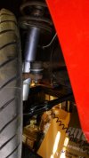
Then undo the nut and rest the tie rod end as shown on the upright. Then with a screwdriver tap the boot off.
removing tie rod boot.jpg


Flip it back over and take a look. Ouch....mine was all dry inside...no grease in sight !!! Just some hardened bits. Left like that....surely the joint would not have lasted long at all !!!

tie rod end as found.jpg


At this point.....check again the joint for any play. Easy to tell now.

Clean it up as best you can with rags and a small wire brush:

tie rod end after cleaning.jpg


Work in some grease as best you can.

tie rod end after greasing.jpg


Clean off the landing spot of the new tie rod end boot. And apply some grease to the small inner end of the boot. Place new boot in position.

tie rod boot in position.jpg


As this boot type is pressed on to the joint....you must then drive it home. Use a 30mm deep socket and with a hammer, tap it on until it is firmly seated

tie rod boot driving home.jpg

tie rod end boot in final position.jpg


Flip it over and install into the upright with the new nyloc from the kit. Note !!! it takes a m10 x 1.25 short type nyloc !!! There is also in the kit a m10 x 1.25 TALL type nyloc which is for the lower control arm pivot bolt. Make sure you use the correct short type here on the tie rod end...and leave the TALL type for later !!!

Torque the nut to 25 ft-lbs...and you are done !!! That was easy.....

all done:

tie rod boot done.jpg


Now the above is assuming that your X has the press-on type boots as shown. But most replacement tie rod ends seemed to have come with a boot that was instead held on with two funky wire clips. I will explain how to deal with them in the next episode.


In the next installment we will move onto the lower control arms and radius rod. Stay tuned.....
 

Attachments

  • tie rod boot done.jpg
    tie rod boot done.jpg
    63.5 KB · Views: 190
  • tie rod boot done.jpg
    tie rod boot done.jpg
    63.5 KB · Views: 190
Last edited:
Work in some grease as best you can.
There's something I've seen restoration shops do when a rare car does not have new joints available and the old one is marginal. Personally I've never tried it, and really have no plans to. The concept is interesting but might be questionable.

Basically they modify the joint slightly to make it "serviceable", like some ball joints are for other makes of vehicles. They drill and tap the back side of the joint and install a zerk fitting. Then a grease gun can be used to fully lube inside the joint. It requires a certain type of bit and tap, and you must know what you are doing to avoid damaging the joint in the process.

It would look something like this when done right:
2011-12-15 11.09.49.jpg
 
I found a decent picture showing why the idea of adding a zerk fitting to a ball joint may not always be a good idea. Aside from knowing how to do it properly, and avoiding getting metal bits inside the joint, it really depends on the design of the joint if this will even work. Naturally some joints are made to be serviced, but some are made where the bottom side (away from the stem) is sealed, so the grease will not travel into the joint. However there are others that weren't designed specifically with a zerk fitting, but they will work if one is properly added.

download.png

The one on the left won't work because the grease can't get through. The one on the right is one design where the grease can travel into the joint (there are other designs that also can). I don't know how the X's joints are designed internally, so not sure how it would work on them.

I also should have noted this isn't intended to repair a worn or bad joint. It simply allows some joints to be lubed a little better. It's always best to replace the joint with a new one if it is worn or damaged.
 
Okay...moving on to the main part of the front suspension re-fresh.

It is important to note that this part can be done quite easily whilst leaving most of the front end components in situ. There is NO need to remove the brakes, hubs, uprights, struts, or steering !!!!

Start..if you can...by soaking the nuts and bolts to be removed in your favorite penetrating fluid for a day or so..

It is important to remove the nut at the front end of the radius rod first ( 19mm wrench or socket ). If you undid the bolt where it joins the control arm first....the whole radius rod would just spin of course and you would have difficulties removing that nut later. So remove that nut entirely first.

Then ....undo the big nut from where the radius rod joins the control arm. You may then find the bolt there can be difficult to remove. It is NOT threaded into the control arm..it just slides through it. But may well be seized in a bit. Apply some more penetrant fluid....or just use an impact wrench on the head of the bolt from above. Go back and forth....it will soon come loose. Remove that bolt and then remove the whole radius rod assembly from the car. Leave the small 8mm bolt on the strap on the control arm for now.

Note at this point there are several bits at the front of the radius rod. Two big washers, two rubber bushings, a steel sleeve, and likely a washer or two or three at the back end of those bits. Those washers are to set the caster setting. Note how many are on each side of the car.

Now undo the nut on the ball joint. of the control arm ( 19mm wrench again ). ..and separate that joint just like you did onto the tie rod end above. Using your favorite tool or method.

Undo the nut and bolt at the inner end of the control arm. 17mm wrench size. The entire control arm will now fall off.

That is all. Pretty easy , eh ?

Now gather up all those bits on your workbench for closer scrutiny.

The radius rod will likely be just fine. It should be perfectly straight. Unless accident damaged or bent by someone jacking up the car from the middle of it.... The exposed threads on the end of it may be crusty...so if need be run a die over them. M12 x 1.25 thread size. The rubber bushings will no doubt be quite perished and hard or cracked. These were mine below. Hard as rocks and quite worn and distorted. My old ones are the outside ones in the pic. Compared to 2 new ones in the middle:
radius rod bushings old vs new.jpg


Take all the steel components and examine, clean, paint/powdercoat/plate...as you see fit.

At this point.....it is optional to remove the bracket at the front of the car that holds the radius rod. Held on by three bolts with - strangely for Fiat - a 14mm head. But there is no need to remove it unless you want to paint it along with everything else.

But.....on the hole in that bracket that the radius rod goes through...there SHOULD be a black plastic grommet !!! That locates the radius rod and prevents metal-to-metal contact at that point. Being 40 year old Italian plastic...it has often deteriorated to the point of being missing entirely !! If still there in decent shape..you can leave it there if you wish. Or replace it with that fancy new blue grommet in my kit. See pic below with it in place:
radius rod bushing.jpg
radius rod bushing blue.jpg


Moving on to the lower control arm. Now on the bench. Apply lots of penetrating fluid and or heat, and remove that small bolt that holds the little strap to the top of it. Or...you can just leave it in place as is.

Then screw the nut back onto the ball joint a few turns ( to make it easier to manipulate it ) ...and yank on the ball joint to check for any play. It may be stiff...that is okay...and of course it will swivel.....but if you feel any in-and-out play in the joint...I'm afraid to say the control arm is shot and you will have to look for a new control arm.

If okay....now remove the dust boot. If it is a press-on type as the above tie rod rod end boots......just knock it off. If..however...it is more likely the type of boot that is held on by two funky wire clips instead.....like the one below:

front control arm boot.jpg


then proceed as follows. It will be easiest if the control arm is held in a vise at this point. At the big end of the boots...there is a flat wire-wound clip. Very carefully..with a dull small screwdriver...dig under the end of the clip and pry it out a bit. Then insert a couple of zip ties under the end of the clip:
zip ties.jpg


and wind the clip out and off. Use some care here as you MUST re-use these clips with the new boots. 99% of the time there are still in decent shape and can be re-used. I was unable to find a source for new ones.

The boot...complete with the clip still on the small end...can now be yanked off the ball joint. Save that small clip for re-use again too.

As with the above tie rod end..you will likely find very little nice grease still inside the ball joint. As above...clean it out really good...and hope to find a shiny ball still inside.

Look really carefully and you will likely see - only on the later type ball joints - 4 evenly spaced small square slots in the plastic inner liner of the ball joint. Try to blow these out with compressed air. These are - I figure - reservoir channels meant to be filled with grease and disperse the grease as the joint swivels. So I went to the drug store and got a disposable needle with a good sized gauge type. I filled it with grease from the tube and stuck the needle down each slot as far as I could and filled those slots with grease. Seemed like the thing to do. They are quite cheap to buy...after you have attempted to explain to the pharmacy why you need one. You will get strange looks... I would have included one in the kit.....but thought customs might have taken a dim view of that.....
needle 1.jpg
needle 2.jpg


At this point it seemed prudent to put the old nut back on. When the nut goes on enough to engage the nyloc part, at that point turning the nut more will result in the whole shaft and ball now turning inside the socket. Crank the stud over to as much angle as possible and continue to spin the stud. That should then distribute the new grease well into the bowels of the socket. Do that at various angles and keep spinning the ball. Re-fill the slots with your needle.

But I have jumped a little of of order here. Do indeed clean out the joint...but you will likely want to clean and paint the control arm BEFORE you start re-greasing it. But do check out that the ball joint portion is good before bothering to go much further.

At this point turn your attention to the inner bushing of the control arm. It is likely hardened or cracked. So replace the bushing with a fresh new one.

To remove the bushing....I found it easiest to trim off one end of the protruding rubber. Then drill some holes in the rubber parallel to the steel sleeve. And then push out the sleeve in a vise. CAUTION - you must re-use the old steel sleeve ( I was unable to source new ones anywhere ). So do take some care with the steel sleeve so as not to mangle it. When pressing on it, perhaps use an old 10mm bolt stuck in it, so you are pressing on the bolt head and not directly on the sleeve.

And...do check that for some reason the sleeve is not worn on the inside. And that the 10mm pivot bolt is not worn either. Either of these ( and/or the holes in the chassis the bolt passes through ) could possibly be worn if that bolt had been left loose by a PO , and the control arm was actually then pivoting on the bolt, and not by twisting the rubber bushing as it should be !!!!

Remove all the old rubber and clean up the inside of the control arm and the sleeve.

At this point you can wire brush the control arm and re-paint it. DO NOT powder coat it as that process WILL melt the inside plastic socket of the ball joint and render it useless !!!!

Now you will be faced with the task of pressing the new bushing into the control arm. This can be a little tricky and use your entire vocabulary of vulgarities...but it is not as bad is it first appears. The trick is to install the rubber bushing first and THEN the steel sleeve. I suggest lots of water and dish soap. Others have suggested a silicone lube...but in the end this bushing works by only twisting the rubber...and NOT by any motion between the rubber and the control arm or the steel sleeve. The water and dish soap will dry out - silicone lube wouldn't. So lube it up really good and press in the bushing in a vise. First pry the end of the bushing into the hole of the control arm.....and squish it in with the vice. When the rubber starts to reach the other side of the control arm...you will have to use a large socket to allow room for the rubber to come through. Sorry I took no pics of this process...but you will figure it out.

After...the bushing is now in proper position in the arm....then you will have to press the steel sleeve though the center of it. The hole will look too small...but it will go. Again...lube everything up well. The trick is to find something like this in your toolbox to act as a leader to "blaze a trail":
socket.jpg


with the steel sleeve following it. Press the sleeve sleeve all the way through - in a vise - with some appropriate sockets and spacers. You will figure it out.......

Now.... go back and finish cleaning out the ball joint. And pack it with grease as best you can.

Then grab the new boot and transfer the small steel ring ( at the small end of the boot ) from the old boot to the groove on the new boot. Pack the inside lip of the small end of the new boot with grease. Look closely and you will see there are grooves on the inside of the small lip. These are to lessen friction at the point - and to hold a reservoir of grease - as at this interface the stud must be able to swivel inside the boot as the steering turns. Otherwise the boot ( if held too tightly on the tapered ball joint stud ) would just twist as well and tear. Thus you want the tension applied by the boot and the steel ring to be tight enough to seal out water and debris, but loose enough to still be able to slide and swivel.

So take the boot ( remember with the clip already on the small end ) and slide/twist it into position over the stud and work it over the lip of the control arm until it is seated properly in the groove. Then carefully install the big clip in a reverse manner of how you removed it. Take care not to puncture the boot. And ensure the clip is seated properly.

If your control arm has a press-on type boot - like the above tie rod end - just follow the instructions in the tie rod boot tutorial above to install the boot. The same except you will need a larger socket with an ID that clears the rubber part of the boot but applies pressure on the integral steel ring portion. - and press the new boot on. I found a 36mm socket worked perfectly

You now have a fully rebuilt control arm !!!

Then just bolt the control arm and radius rod back on the car. Using , of course, all new nylocs. And do apply some anti-seize to the shanks of the control arm bolts to prevent them from seizing in the future.

The inner pivot bolt takes a m10 x 1.25 special TALL type nyloc. Which is - of course - well - TALLER than a regular nyloc. There are 2 of them in the kit. The 2 regular ( shorter ) nylocs in the kit are for the front outer tie rod ends. Do NOT mix them up !!!. IMPORTANT - when installing this pivot bolt/nut - do NOT fully tighten it until the suspension is back together AND the car is sitting on the ground at final desired ride height !!! Only at that point should it be tightened up fully.

Then re-connect the lower ball joint to the upright. with a new m12 x 1.25 regular height nyloc. There are 2 only of them in the kit. Do NOT use a tall type nyloc nut there as there is not enough thread length on the ball joint to accommodate one. Torque to 58 ft-lbs

Then slip the radius rod into position. For the big nuts at each end of it use a m12x 1.25 TALL type nyloc. There are 4 of them in the kit. Again...do NOT fully tighten that nut where the radius rod joins the control arm until the car is on the ground at desired ride height. At the front end of the radius rod of course first loosely place on the end of the rod - first the original number of small caster washers as was there - then one cupped washer - then the steel sleeve - then one of the bushings. Stick that through the hole in the radius rod bracket. Then slip on the other rubber bushing followed by the other cupped washer. Then spin the m12 x 1.25 TALL type nyloc on. And tighten it down. This will become progressively tougher as the rubber bushings compress...and they will compress a lot. Eventually the nut will stop solidly against the washer and steel sleeve ( which prevents you from compressing the rubber bushings too much ). At that point you can torque it to its final setting of 51 ft-lbs

Put the wheels and tires back on and lower the car to the ground. Bounce the front end a few times to settle the suspension.

Then reach in and tighten the inner control arm pivot bolt to 29 ft-lbs. And the radius rod to control arm nut to 51 ft-lbs.

That is it .. you are done !!! That was pretty easy wasn't it. ?

It is recommended that you perform this service every 40 years :)

Afterthoughts........the most time consuming aspect of this will be the cleaning/de-rusting/painting of all the components involved. If...you are after the "survivor" vibe......just install new bushings and boots. If...you desire everything to look shiny and spiffy...I can highly recommend using Evapo-Rust: https://www.harborfreight.com/1-gallon-evapo-rust-rust-remover-96431.html. Available in Canada at Princess Auto. In the USA at Harbor freight and I think Home Depot. The stuff is amazing. Just find a plastic pan and submerge all the rusty bits in it for a couple of days. You will be shocked at how they come out. I wouldn't submerge the whole control arm in it..but you could find a tall narrow plastic jug and soak everything except the ball joint end. Or use a wire brush or wire wheel in a drill or bench grinder. Then paint as desired.

And if...you end up finding your control arm has too much play and must be replaced.....perhaps keep the old one around. Just might come in real handy for someone who mangles their wire clip or steel pivot sleeve. Those little bits cannot be found on their own.

Do feel free to ask any questions...or make any comments. Or add some tips that might help someone out......

Next episode...we'll do the rear suspension....stay tuned....
 
Last edited:
On to the rear suspension....

Again...do note this can be done whilst leaving the brakes, hubs, uprights, and struts in situ.

Although...you will likely find the job easier if you have dropped the engine and tranny for any reason. Or have removed the driveshafts. Or if the suspension has been dropped as part of a restoration. Or if you are doing wheel bearings or something....

The job is fairly simple....and I wont go into full detail here. And dont have many pics of the process. Mostly just a few guidelines and tips here.

Basically....you will have to remove the rear arms from the car. Although just changing the A arm bushings can - in theory - be done on the car with a special tool that presses them in and out. But lets assume you are also going the service the ball joints and install new boots...That is best done with the A arms on the workbench.

First.....you will find that to have room to remove the disconnect the ball joint.....the driveshaft flange is in the way. Unbolt those Allen head bolts that hold the driveshaft onto the hub flange. And tie the driveshaft out of the way. Then ....from the wheel side of the hub....unstake that big hub nut. Undo that nut with a 36mm socket. Correction - it is a 30mm. Easiest to do that with an impact wrench. Then the stub axle can be just slid out of the hub and set aside.

Then undo the ball joint nut - 22mm wrench or socket - and separate the ball joint from the upright.

Undo the cotter pin and nut where the toe link joins the upright. Pop that joint apart.

Then undo the two big nuts and bolts - 22mm wrench again - where the A arm joins the chassis. And remove the A arm from the car. IMPORTANT - you will note at this point there are a bunch of thin washers on each side of the bushings that will fall out. Note and record their number and position.

Transfer the A arm to the bench. Remove the toe link bolt at the inner end set the toe link aside for now.

Check - as you did in the front - the ball joint carefully for any play.

Replace the old bushings in the A arm. This is best done in a shop press.

Clean/de-rust/paint the A arm as you see fit.

Remove the old boot from the ball joint - just like you did in the front - and clean and re-grease as best you can. Install new boot.

As for the toe link assembly...how far you go there is up to you. Of course you should clean/service/re-grease/install new boot - on the outer joint as a minimum. If....you decide to take it apart....first measure carefully and record how much each end is into the sleeve..so you can put in back later the way it was..so as not to disturb the toe setting. Or at least to get it close enough until you get an alignment later....

Why would you want to take the toe link assembly apart ? Perhaps just for cleaning/de-rusting/painting. But more crucially you may well find - as I did - that the internal threads of the sleeve are so rusted that adjusting the toe setting later is impossible. And thus the sleeve will NOT adjust tighter than its existing setting. Read my thread here for more insight:

If yours - like mine - was too far rusted after cleaning or penetrants or Evapo-Rust.........I do have here two complete sets of taps and dies to correct the problem. Contact me if you would like to buy or rent a set.

You can decide at this point if you want to change the inner toe link bushing. It is NOT included in my kit.

When done all that.....just re-install the A arm and toe link back on the car. Do smear some anti-seize on the shanks of the A arm and toe link bolts to prevent them from seizing into the bushings in the future. Install a new V ring seal ( included in the kit ) on the stub axle while it is out.

Torque the ball joint nut to 61 ft-lbs.

Replace those thin washers on the inner A arm bolts in the same number and position as they came off. This may not be possible as the new bushings may well not have been pressed in to the exact same location as the old ones. It is more important that the same number be put back at each bolt. so...if there were originally say 4 washers on one side of the bushing and 1 on the other...but it wants to have 3 on one side and 2 on the other....that is okay.

Again....like the front and for the same reason...do NOT fully tighten all the bolts until everything is assembled and the car is back on the ground and the suspension has settled to its final ride height.

Final torque setting are :
Inner A arm nuts 72 ft-lbs
Inner toe link nuts 51 ft-lbs
Stub axle nut 159 ft-lbs AND THEN STAKE. It is a good idea to use new stub axle nuts or swap the stub axle nuts from side to side so the staking will likely now be in a different position.

Good luck. any input here or further tips or discussion is welcome.
 
Last edited:
unstake that big hub nut. Undo that nut with a 36mm socket.
Ready to tackle this, starting with the rear...

First, I have a '78 and it's a 30mm nut.

Second, with the car on jackstands with wheels and brakes off how do I keep the driveshaft from rotating?


Roy
 
Oh....and my instructions are for a 1500. Not sure if you have to remove the driveshaft or stub axle on a 1300..for clearance to get the ball joint apart.
 
Just zip it off with an electric or air impact wrench...

Well, whadda know, it worked! Axle did turn with it but it still came off.

Since I'm dropping the engine I thought it would be a good plan to remove the axle. Unfortunately I DID NOT drain the transmission before removing the transmission/shaft boot....

IMG_1504.JPG


:oops:

And you may be wondering why there is a 2x4 holding up my suspension... Well, the strut is out as well as the A-arm bolts. Gave it a few tugs but no go. So now contemplating how big a BFH I'll need 🤔 :D

Roy
 
Well, whadda know, it worked! Axle did turn with it but it still came off.

Since I'm dropping the engine I thought it would be a good plan to remove the axle. Unfortunately I DID NOT drain the transmission before removing the transmission/shaft boot....

View attachment 50945

:oops:

And you may be wondering why there is a 2x4 holding up my suspension... Well, the strut is out as well as the A-arm bolts. Gave it a few tugs but no go. So now contemplating how big a BFH I'll need 🤔 :D

Roy
Nice work. Suggest long pry bar as a next step to drop your A arms. I like you have an early car (though I've converted to five speed). Unlike you but like many here preceding us, two of my four A arm bolts are seized in place. There are some good threads about removal for those of us vexed as I am. Amazon just delivered a large forged C clamp with which I will attempt to employ to back the bolts out without destroying the frame ears. Will report to you all as to outcome.

 
Well, whadda know, it worked! Axle did turn with it but it still came off.

Yes..an impact gun is a wonderful thing !!

And you may be wondering why there is a 2x4 holding up my suspension... Well, the strut is out as well as the A-arm bolts. Gave it a few tugs but no go.

No worries. A pry bar - a wonderful thing too - will have it off in a jiffy... Just be careful as there are a bunch of shim washers in there. Take a note of how many and where they came out of !!!

Unlike you but like many here preceding us, two of my four A arm bolts are seized in place. There are some good threads about removal for those of us vexed as I am. Amazon just delivered a large forged C clamp with which I will attempt to employ to back the bolts out without destroying the frame ears. Will report to you all as to outcome.

Again - if you can get one in there...an impact gun is a wonderful thing. Just zip back and forth......it will spin it out.....
 
Findings and progress report for the good of the order. Left forward A arm mount bolt was super seized to the inner bush sleeve. Sledge with drift wouldn't get it to yield even after applying some heat. It might have been possible to free it with the large C clamp press but to get a clean shot would have required either removing the fuel tank or the transaxle. So studied the forum posts and broke out the Sawzall and high speed disk cutting tool. Took some patience and planning so as not to inflict carnage but success in the end. POR15 is on the way with associated Chassis Black topcoat. Meanwhile dropped the arms off at the local Mercedes mega dealer where my excellent neighbor runs the #1 mechanics bay, he will press the old bushings out and load in the new ones. I cleaned up the areas in question with a wire wheel in order to give him the best chance of success and clear view of the proceedings. Also dismounted the rear tie rods to check the inner bushes, make sure the adjustment sleeves will be free to turn, and service the ball joints. The left side ball joint was perished, under the boot discovered an amazing paste the color and texture of mud. This ball joint yields to motion, was loose and moves a bit vertically, which in addition to the 45 year old arm bushes could easily explain the fault at high speed when braking hard and observing course change. Those hub locating ball joints are not readily available economically relative to front tie rod bits etc. Eurosport-UK has them so one is on the way along with other miscellany. When I get the arms back I'll prep them with wire wheels on a buffing tool, then treat with POR.

I see now how the ball joint boots on the tie rods work....there's a mounting groove and wire spring retainers. However, I don't yet understand how the boots mount on the A arm lower ball joints. Cut the old ones off with a utility knife, they were super secured at the bases and look as though integrated to the ball joint body.
 
I see now how the ball joint boots on the tie rods work....there's a mounting groove and wire spring retainers. However, I don't yet understand how the boots mount on the A arm lower ball joints. Cut the old ones off with a utility knife, they were super secured at the bases and look as though integrated to the ball joint body.

Hi Jim. Thanks for posting your progress.

On your rear a arm ball joint boots - as they are 1300 arms - the boot has an integral steel ring bonded to it. The boot should look like this:

press on boot.jpg


That type of boot gets pressed on firmly to the ball joint. But can be removed quite easily. Just carefully knock it off. Go back and look at the pics in my first post in this thread. The process is explained about the front tie rod ends - a different sized boot but works exactly the same. Just tap it off. That steel ring is bonded the the rubber of the boot. It may appear to be part of the ball joint itself after all these years..but it is not !!

You should NOT have just cut it off !!! As those size boots are NOT available anywhere these days as far as I am able to tell. And I tried VERY hard to find them. They were the only boots I was unable to find or have re-produced. EDIT - I have now found those boots - see my newest kit listing !

You cannot use the 1500 style boot there, as the 1300 and 1500 ball joints are machined differently in the spot the boot lands on the joint. Look closely at the pic below.
x19 rear arms.jpg


Note the 1300 type joint on the left. With the straight boss where the ring presses onto. That steel ring on the boot is an interference fit onto the ball joint. And thus the boot must be pressed on. Easy to do by just tapping it on with an appropriate sized socket that clears the rubber but contacts the steel ring. I show you how above.

Note the 1500 type joint on the right. You can see there is a groove machined into the ball joint The 1500 type boot is pure rubber and has a lip that seats down in that groove. And is secured in place by a funky wire wound clip. Look above for pics of that style boot and you can see how it works.

The two different boot types are NOT interchangeable !!! If you tried to use the 1500 boot on a 1300 joint...there is nothing there to secure the boot. Without that machined groove, the big end of the boot will just pop off the joint when the suspension moves throughout its travel and the joint swivels....

Hope this explanation helps you understand how the boots fit and why. Doug
 
Last edited:
Hi Doug -

Much appreciate your feedback and clear explanation. Yes I should not have cut off the old boots. Here’s why I did and this may be useful to others in the future:

When I swapped in my freshly built 1500 / five speed, I had deferred the A arm bushing job, but did observe the failed ball joint boots. Since as you noted stock boots are no longer available, I installed the silicone aftermarket slip on boot covers as some protection / preventative. Trouble came when I went to take everything apart again to perform the bushing job. With the silicone slip-ons, I could not get my ball joint breaker tool in between the hub carrier and the ball joint. So I had to cut off the silicone slip- ons and further sacrificed the already marginal OE boots.

Yesterday I retrieved my A arms from friends shop bushings are now installed. Will next separate the OE boot retainers, paint the arms and await (hopefully) rare as hen’s teeth correct boots from The Netherlands you kindly identified.

The sawzall job on the one A arm bolt knowingly damaged two A arm shins but I was able to source new correct factory shims. And the large M14 flat washers that reside outboard of the chassis mounts - some were non existent or incorrect so sourced all new from McMasters Carr.

Getting closer to glory.
 
Last edited:
Here you can see the POR15 treated arms plein air foam brush shadetree style paint. Before that I knocked off the ball joint boot flanges, one in the foreground. For clarity, this flange / ring has had its boot cut away, normally the boot is captive and integrated with the press on flange.

Also thoroughly cleaned and checked the rear tie rod adjustment sleeves, ball joint end and bushing end. Fortunately, the adjusters are completely free and work beautifully, likely due to the former dynamic passive anti-corrosion system provisioned by the old four speed that leaked like my old yellow English Labrador and OE NOS Prisma 1500. Treated the one good tie rod end ball joint to Doug's cool grease injection, and installed the new perfect correct boot from his kit with the spring thingy of which I had one on the car from the original left side ball joint.

Later today the arms will receive POR chassis black, then they'll be ready for the ball joint boots from Holland.

boot flange.JPG
 
Rear tie rods after cleaning and wire wheeling, prior to POR15. Note the lower right is the new ball joint sourced from Eurosport-UK. Ordered that bit 6 September it arrived in three days! All the way to the west coast from Great Britain.

tie rods.JPG
 
Boots finally arrived for the A arm ball joints. They are correct. Pressed them on with tool that happened to have a perfect sleeve size. You may observe the POR15 + chassis black topcoat.
boots install.JPG
 
Back
Top