Temp gauge rising

I have a second fan I haven’t installed yet, I need to replace my thermostatic switch in the radiator anyway so I am going with the VW two temp switch at a bit lower temp for the first stage. This switch has a contact for 85C and and another at 93C to turn on the second fan (both fans should be on a relay).

Hopefully this will yield a bit more heat rejection than what I have now.
 
Last edited:
Just went thru this also. I installed a new vikauto radiator along with a new thermostat and a water pump. In my case the biggest difference came with replacing the water pump. I have bled the rad many times and never got much more than a few bubbles of air out. I dont believe this makes much if any difference.
RV
Guelph On
 
Pretty sure my system is working properly with a newer aluminum radiator, pump, and thermostat. Rock steady at 190 on the road but creeps up to about 200 during long idles in hot weather or sitting at a light on the freeway off ramp. Fans kick in at that time as well. The occasional bump over 190 seems related to lower coolant flow at idle rpms.
 
Jay has two cars a lot like our X1/9s, same designer, same coachbuilder. Follow his advice starting at about 3:55 in this video.

I've been to Jay's garage a couple times, spent a morning with him, one on one discussing several of his "special" cars. He is a hard core knowledge freak, and will discuss in detail how he deals with such mech issues. It's like hang'n out with Bill Nye for cars. I like how he accepts the fact that these cars have issues you have to live with.

I feel the same about my own vehicle. Heating/cooling was never a problem which could not be overcome with sensible maint. Make sure timing is good, all cooling components are in good shape, then bleed, bleed, bleed. Did I say bleed? Even then, she might still piss a little fluid every now and then when pushed real hard. I just relaced my entire engine and cooling system. I bleed the rad upon returning to the garage after every ride. I'm getting close after a few bleeds, now she stays pretty cool even in traffic, even with some advance dialed in.
 
BTW, Jay owns at least one Fiat that I saw (Topolino), but still insists on calling our cars "X nineteen's". Makes me nuts.
 
...but still insists on calling our cars "X nineteen's"

my younger brother had a Merkur XR4Ti that he pronounced "exrati" and that drove me nuts (attached image shows the badge - not my brothers car).
8020020-1985-mercury-mekur-xr4ti-std.jpg
 
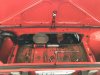
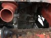
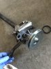
All of the FI cars have wiring for two fans, the system to triggering the two fans are different systems.

Depending on the draw of these new fans, you may be able to just run them both at the same time through the existing relay and wiring, adding the needed wiring for the new fan to the existing power supply and ground of the old single fan.

The one fan would be driven by the thermostatic switch in the radiator and the other wiring system is driven by the AC being enabled through a switch in the AC system.

One can use the system for the AC (the majority of the wiring is present in all FI cars) to trigger the second fan using a switch inside the car or one could use a dual temperature thermostatic switch in the radiator to trigger the second fan. VW used dual temp thermostatic switches to start the one fan at 185 and the second at 195 (as I recall), one could also add an override switch inside the car to turn on the second fan at will.

I would look at the wiring diagram to parse out how to use the existing wiring to drive the second fan if you go that way. There is wiring for a relay in the fuse box area and wiring to support it out to the fan, you would need to decide how you wish to trigger the relay and adjust some of the wiring to suit.

Images below from the ‘80 wiring diagram:

93BDC406-F161-4F7B-899B-A168A4644B27.jpeg 79B83BA2-3F4B-4FFB-9C6E-91BAEF7800FD.png FD9EA4A1-1695-4621-AD52-B3B10AFC8D60.jpeg

I would print the wiring diagram out, identify the wires on the diagram, verify them on your car and then put a relay (standard relay nothing special) in place in the fuse box, put a fuse in the requisite position (13), attach the new fan at the far end, decide what wires you will use to go from the relay to the new switch and good to go.

The more you can use that which is existing, the easier your life will be (fewer wires to run back and forth) and likely the more reliable the solution will be as well.
 
What I found interesting is that cars from '80 onward with AC are wired so that when either the radiator thermoswitch or the condensor fan thermoswitch are triggered, both fans will turn on, yet each fan retains its own separate relay.

On page 18 of the '80-'81 EDM you'll see a white/black wire coming off of Pin 86 on the cooling fan relay, with the notation "Air Conditioning Page 61"

This wire links the two systems and causes both relays to energize when either the radiator fan thermoswitch or the condensor fan thermoswitch is triggered.

In other words, there is never an instance where only one of the fans will be on if the system is working properly. My '85 and '83 with AC were/are wired like this as well.

I installed a switch to manually turn the fans on. All I did was splice into that wht/blk wire coming out of the relay panel attached to Pin 86 on the cooling fan relay. I used a spare courtesy light switch and installed it in one of the spare switch sockets on the center console. For ground, I just spliced into one of the grounds for one of the other switches on the center console. This circuit only needs to handle a a handful of mA to trigger those relays so it doesn't really matter where you tap into ground or what gauge wire you use.
 
I used the most direct route obvious to me, with the wiring and second fan already in place and the newer type fuse box; I put a 20-amp switch I already had across the relay socket's switched terminals. The switch comes out between the console and the electrical drop tray.

When upgrade time comes, I'll do the VW 2-temp switch.IMG_1038.JPG IMG_1039.JPG
 
Hmm on my 86 I do not see any wires for the 2nd fan (got the fan mounted and have gone no farther yet.) (does not seem to help cooling at all without wires running to.
 
What I found interesting is that cars from '80 onward with AC are wired so that when either the radiator thermoswitch or the condensor fan thermoswitch are triggered, both fans will turn on, yet each fan retains its own separate relay.

On page 18 of the '80-'81 EDM you'll see a white/black wire coming off of Pin 86 on the cooling fan relay, with the notation "Air Conditioning Page 61"

This wire links the two systems and causes both relays to energize when either the radiator fan thermoswitch or the condensor fan thermoswitch is triggered.

In other words, there is never an instance where only one of the fans will be on if the system is working properly. My '85 and '83 with AC were/are wired like this as well.

I installed a switch to manually turn the fans on. All I did was splice into that wht/blk wire coming out of the relay panel attached to Pin 86 on the cooling fan relay. I used a spare courtesy light switch and installed it in one of the spare switch sockets on the center console. For ground, I just spliced into one of the grounds for one of the other switches on the center console. This circuit only needs to handle a a handful of mA to trigger those relays so it doesn't really matter where you tap into ground or what gauge wire you use.

Cutting the interconnecting wire will allow you to have them work separately based on the control system you choose to create.
 
Excellent feedback guys!! Thanks! I’d like to basically have my fans work as usual but have a simple manual override switch that controls both.
 
Also, I’ve started the reassembly of the pump and thermostat and wanted to share some pictures.
The service manual says to remove the service panel in the rear trunk and let me tell you, that is a very worthwhile thing to do. Also, you must remove the pump and housing from the block at the same time cause if you try to remove just the pump, it will get stuck between the housing and the right side frame. Doh!!!
You can see in the pictures the old pump impellers are slightly shorter than the replacement vikauto pumps impellers. Perhaps due to wear over 36 years?? Not sure.
 

Attachments

  • 2A8E08CD-7B29-42E2-8955-82B3DB5218FC.jpeg
    2A8E08CD-7B29-42E2-8955-82B3DB5218FC.jpeg
    222.6 KB · Views: 119
  • 18CAEE8D-A1B4-4052-BFD9-F5026DB76C72.jpeg
    18CAEE8D-A1B4-4052-BFD9-F5026DB76C72.jpeg
    251.3 KB · Views: 103
  • D65ED7AF-2BAC-48C1-B6BE-CF2E7450165A.jpeg
    D65ED7AF-2BAC-48C1-B6BE-CF2E7450165A.jpeg
    296.2 KB · Views: 117
  • 25D2D21C-F341-4661-A772-EC8BAB7CED72.jpeg
    25D2D21C-F341-4661-A772-EC8BAB7CED72.jpeg
    320.2 KB · Views: 109
  • 92FAB489-FF9F-47CD-9117-2FAD65BD2F7D.jpeg
    92FAB489-FF9F-47CD-9117-2FAD65BD2F7D.jpeg
    389.4 KB · Views: 112
  • 5F96D5BD-EEF5-43EB-B528-B4D8F198930A.jpeg
    5F96D5BD-EEF5-43EB-B528-B4D8F198930A.jpeg
    113 KB · Views: 107
  • 5E618C82-14A1-4D18-A147-83CFFEC8DB35.jpeg
    5E618C82-14A1-4D18-A147-83CFFEC8DB35.jpeg
    248.3 KB · Views: 103
  • E587F319-DC5A-4D61-A337-4EBBA2860B91.jpeg
    E587F319-DC5A-4D61-A337-4EBBA2860B91.jpeg
    124.8 KB · Views: 106
  • 60FB0172-F673-4A56-A4CB-42DB2A945936.jpeg
    60FB0172-F673-4A56-A4CB-42DB2A945936.jpeg
    187.5 KB · Views: 108
  • 5FD7F1EB-BBF1-405E-B73F-EE90852B28C1.jpeg
    5FD7F1EB-BBF1-405E-B73F-EE90852B28C1.jpeg
    120.8 KB · Views: 107
You can also see that the trunk pan is pretty rough. That will be remedied this winter hopefully with the help of the talented Tony K. The plan is to replace the rot with a custom stainless bead rolled panel.
 
More pictures...
Also a side note, the thermostat seal available from viks is incorrect. The original one is slotted and fits around the rim of the thermostat itself. Luckily mine was in good shape and I’ll be able to reuse it. I’ll post pictures of that later...
 

Attachments

  • 34C01DE2-710A-4992-A830-00686D43CCDB.jpeg
    34C01DE2-710A-4992-A830-00686D43CCDB.jpeg
    171.1 KB · Views: 82
  • 6EDFA39D-D438-48CD-8FB5-D043433B0851.jpeg
    6EDFA39D-D438-48CD-8FB5-D043433B0851.jpeg
    306.5 KB · Views: 94
  • 7B4D5988-E9F3-400C-BB2D-7E2A7CE1DEF3.jpeg
    7B4D5988-E9F3-400C-BB2D-7E2A7CE1DEF3.jpeg
    174.7 KB · Views: 87
  • B20955BF-2C78-4E1E-95B3-F3BC72ED510E.jpeg
    B20955BF-2C78-4E1E-95B3-F3BC72ED510E.jpeg
    84 KB · Views: 137
  • 59E5F6D9-CB8D-4987-9C9A-F9EC9E3D696D.jpeg
    59E5F6D9-CB8D-4987-9C9A-F9EC9E3D696D.jpeg
    149.3 KB · Views: 96
Also, you must remove the pump and housing from the block at the same time cause if you try to remove just the pump, it will get stuck between the housing and the right side frame. Doh!!!

Looks like you are having lots of fun! :)

If you want to remove the pump and leave the housing in place, put a floor jack under the engine to support the weight, pull the cross bolt from the snail mount, jack the engine up a few inches and the pump should come out. Just FYI since you have already worked around the issue.
 
Back
Top