
You are using an out of date browser. It may not display this or other websites correctly.
You should upgrade or use an alternative browser.
You should upgrade or use an alternative browser.
K20 project off to a good start
- Thread starter Rodger
- Start date
-
- Tags
- box engine swap box k20
Rodger
True Classic
More PO mysteries
I know there are all kinds of strange PO wiring stories out there, but I was not expecting this. I started working on cleaning up the K20A2 wiring harness to get it on the engine before I put the engine in the car. I was going to redo some of the wrapping to get it to look better and when I undid the section with the fuel injector connectors on it, I found that the PO had cut off all of the stock injector connectors at some point, and then resoldered them back on. His solder technique was pretty poor with large lumps of solder just wrapped with electrical tape.
Then I took closer look at the ECU connectors and noted several wires that had been cut and then resoldered, again with very poor technique.


I assume that this must have been done by the original owner of the car, because the person I bought it from was a nice middle aged woman who had bought it with about 30,000 miles on it. I surmise that the original owner had put in larger injectors that required different connectors, then added some aftermarket piggy-backed ECU to allow some custom fuel mapping. Considering that I discovered a Z1 block on an otherwise stock A2 motor, leads me to conclude that he must have overdone it and threw a rod, ruining the original block. I can only hope that someone who knew what they were doing, rebuilt the motor. The original owner must have put the stock injectors back on and took off whatever aftermarket electronics he had on it, then sold the car.
The person I bought it from drove it for 80,000 miles with no issues and it was maintained by her husband who owns an auto repair shop. The engine started fine when I looked at the car and sounded good even though I didn't drive it as the front end was wrecked. I will hope for the best on this one.
I know there are all kinds of strange PO wiring stories out there, but I was not expecting this. I started working on cleaning up the K20A2 wiring harness to get it on the engine before I put the engine in the car. I was going to redo some of the wrapping to get it to look better and when I undid the section with the fuel injector connectors on it, I found that the PO had cut off all of the stock injector connectors at some point, and then resoldered them back on. His solder technique was pretty poor with large lumps of solder just wrapped with electrical tape.
Then I took closer look at the ECU connectors and noted several wires that had been cut and then resoldered, again with very poor technique.
I assume that this must have been done by the original owner of the car, because the person I bought it from was a nice middle aged woman who had bought it with about 30,000 miles on it. I surmise that the original owner had put in larger injectors that required different connectors, then added some aftermarket piggy-backed ECU to allow some custom fuel mapping. Considering that I discovered a Z1 block on an otherwise stock A2 motor, leads me to conclude that he must have overdone it and threw a rod, ruining the original block. I can only hope that someone who knew what they were doing, rebuilt the motor. The original owner must have put the stock injectors back on and took off whatever aftermarket electronics he had on it, then sold the car.
The person I bought it from drove it for 80,000 miles with no issues and it was maintained by her husband who owns an auto repair shop. The engine started fine when I looked at the car and sounded good even though I didn't drive it as the front end was wrecked. I will hope for the best on this one.
Last edited:
lookforjoe
True Classic
That's ugly. It clearly functioned, since the PO drove it for 80K that way, however better to clean it all up now while you have it apart for sure...
Roobus
Orange "K"rusader
That's no good...
But luckily the k20 swap has been around for years and has good suppliers. If you don't want to deal with that mess, you could just go this route:
http://www.hybrid-racing.com/electr...rness-for-k-series-engines-hyb-cwh-01-99.html
But luckily the k20 swap has been around for years and has good suppliers. If you don't want to deal with that mess, you could just go this route:
http://www.hybrid-racing.com/electr...rness-for-k-series-engines-hyb-cwh-01-99.html
darwoodious
Darin Nelson
more options
My nephew-in-law has a K20 powered Honda and he raves about this
LVL2 - MILSPEC 02-04 K-SERIES
It is very high end and a lot of scratch for a harness. The interesting thing is that they're all custom so one could get a length that fits even better thru the X1/9's firewall - could even put a disconnect plug there for the entire harness.
I saw your soldering skills on your instrument cluster work Rodger, so I think just going back over the splices might be your best bet, but thought I'd share the other resource I know of.
Rodger
True Classic
I am just going to resolder those connections by the ECU. I decided to tuck my fuel line to the rail and the wiring harness to the injectors by coming up through the center of the intake manifold like I have seen on a lot of pictures of Honda/Acura cars with tricked out engines. I already have new pigtails for the injectors. Just need some free time, haha.
Sent from my iPhone using Tapatalk
Sent from my iPhone using Tapatalk
Rodger
True Classic
AC Compressor and wiring update
Well, progress on this build continues but slowly. After finding all of the poor solder joints in the engine wiring harness, I went through the whole thing and fixed all of the splices with good solder joints and heat shrink tubing instead of electrical tape. Good thing, as a couple of the splices at the ECU connectors came apart with just a gentle tug. I am amazed that they all held for so many years.

I had been looking at a number of pictures of K20 swaps online and liked the “tucked” look so I ordered some new injector connector pigtails and some braided wire sleeve and redid the injector runs to come up from the center of the intake manifold.

Once I had the engine wiring harness finished, I figured I might as well start figuring out the AC compressor mounting. I have seen photos of the two K20 swaps that MWB did with AC, so I used those as a general guide on where to mount the compressor. The ones that MWB did both used Honda compressors and both cars already had the factory AC installed. I was using an aftermarket Sanden type compressor from Nostalgic Air. This was actually the same compressor that LarryC recommended in his thread on rebuilding his stock Fiat system. I had originally ordered it when I first decided to add AC to this car before it became a K20 swap build. I had spent a bunch of time working on the mount to the 1500 engine along with a Delco alternator when the K20 bug bit. I sent the compressor back to Nostalgic to have them change out the V-belt pulley/clutch for a serpentine belt/clutch to use on the K20. They were very nice about it and only charged me for shipping.
The only place to mount the compressor is on top of the engine in the position where the original power steering pump was. The stock location was below the alternator, but there is no room for it in the X due to the cross member of the frame at the base of the firewall. Also the MWB engine subframe attaches to the original mounting points of the compressor. The compressor is larger than the power steering pump so it has to sit above the intake manifold. It kind of ruins the esthetic of the engine, but I will take cool air over appearance on this one. I cut off one of the little fins on the manifold to get the compressor as close to the manifold as possible.
It took me a while to work out the position to get it level and to get the pulley in line with the others. I ended up cutting up one of the Fiat compressor mounting brackets that I had bought for the 1500 application.

It turned out that the thickness of the metal was just right to get the pulley alignment correct and the large piece I cut out of it put it at the best height and got it as close as possible to the fuel rail. I am a little nervous about the height of it as far as clearing the engine cover and the hose connectors will be very close to the frame below the rear window, but I think it will make it. We’ll see once I try the engine in. I fabricated a custom bracket that attaches to a couple of unused intake manifold threaded holes to support the rear of the compressor.
Once I had it all bolted down, then began the hunt for the correct serpentine belt. It took me a few trips to the local auto parts stores, but I finally found the perfect length with a Dayco 5060590. The K20 comes with a 7 rib belt, but I could not find one in the right length, so I went with a 6 rib which is what MWB includes with their swap kit anyway.


With the engine pretty much ready to install, I put it away for now and turned my attention to the car wiring. I mounted the ECU to the left side of the trunk, using the mounting points for the stock blower motor. I added a bracket to the forward strut to attach the three relay sockets needed. Next is to complete adding the K20 specific wiring to the car wiring harness.

Well, progress on this build continues but slowly. After finding all of the poor solder joints in the engine wiring harness, I went through the whole thing and fixed all of the splices with good solder joints and heat shrink tubing instead of electrical tape. Good thing, as a couple of the splices at the ECU connectors came apart with just a gentle tug. I am amazed that they all held for so many years.
I had been looking at a number of pictures of K20 swaps online and liked the “tucked” look so I ordered some new injector connector pigtails and some braided wire sleeve and redid the injector runs to come up from the center of the intake manifold.
Once I had the engine wiring harness finished, I figured I might as well start figuring out the AC compressor mounting. I have seen photos of the two K20 swaps that MWB did with AC, so I used those as a general guide on where to mount the compressor. The ones that MWB did both used Honda compressors and both cars already had the factory AC installed. I was using an aftermarket Sanden type compressor from Nostalgic Air. This was actually the same compressor that LarryC recommended in his thread on rebuilding his stock Fiat system. I had originally ordered it when I first decided to add AC to this car before it became a K20 swap build. I had spent a bunch of time working on the mount to the 1500 engine along with a Delco alternator when the K20 bug bit. I sent the compressor back to Nostalgic to have them change out the V-belt pulley/clutch for a serpentine belt/clutch to use on the K20. They were very nice about it and only charged me for shipping.
The only place to mount the compressor is on top of the engine in the position where the original power steering pump was. The stock location was below the alternator, but there is no room for it in the X due to the cross member of the frame at the base of the firewall. Also the MWB engine subframe attaches to the original mounting points of the compressor. The compressor is larger than the power steering pump so it has to sit above the intake manifold. It kind of ruins the esthetic of the engine, but I will take cool air over appearance on this one. I cut off one of the little fins on the manifold to get the compressor as close to the manifold as possible.
It took me a while to work out the position to get it level and to get the pulley in line with the others. I ended up cutting up one of the Fiat compressor mounting brackets that I had bought for the 1500 application.
It turned out that the thickness of the metal was just right to get the pulley alignment correct and the large piece I cut out of it put it at the best height and got it as close as possible to the fuel rail. I am a little nervous about the height of it as far as clearing the engine cover and the hose connectors will be very close to the frame below the rear window, but I think it will make it. We’ll see once I try the engine in. I fabricated a custom bracket that attaches to a couple of unused intake manifold threaded holes to support the rear of the compressor.
Once I had it all bolted down, then began the hunt for the correct serpentine belt. It took me a few trips to the local auto parts stores, but I finally found the perfect length with a Dayco 5060590. The K20 comes with a 7 rib belt, but I could not find one in the right length, so I went with a 6 rib which is what MWB includes with their swap kit anyway.
With the engine pretty much ready to install, I put it away for now and turned my attention to the car wiring. I mounted the ECU to the left side of the trunk, using the mounting points for the stock blower motor. I added a bracket to the forward strut to attach the three relay sockets needed. Next is to complete adding the K20 specific wiring to the car wiring harness.
Last edited:
kmead
Old enough to know better
Dang that is sanitary. Nice work.
Much better than you could afford to pay for I suspect and some serious pride in having accomplished it.
Not an AC person myself but this doesn't seem to be too horribly invasive. Certainly have the power to support it with K20, it really bogs my wife's 1.6l Miata.
Looking forward to the next installment
lookforjoe
True Classic
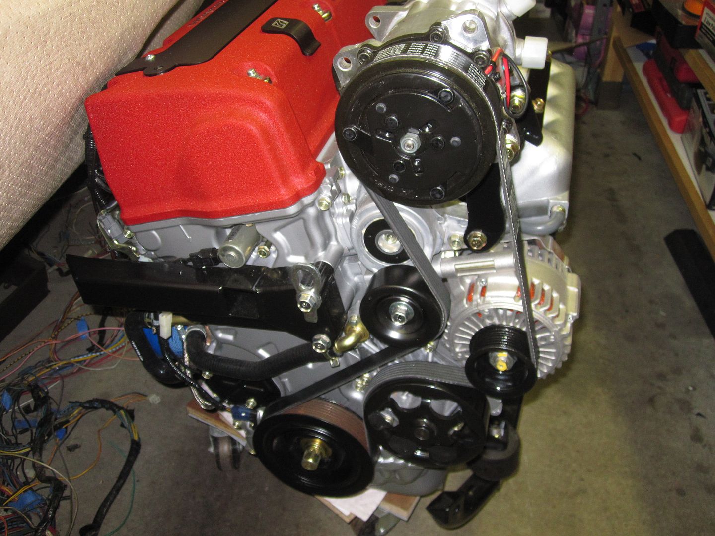
Nice clean work! Serpentine alignment / layout looks great - the large pulley below the Alt - that one doesn't look like it had ideal contact area though... Is that the water pump or an idler? Stock K20 layout has the same coverage though? I presume you didn't alter the belt routing other than bringing it up for the AC?
Rodger
True Classic
The large pulley below the alternator is the water pump. Here is a picture of the engine right after it came out the RSX donor car, showing the locations of the power steering pump and the AC compressor.

Yes, as Honda intended, there is more wrap of the belt around the water pump because of the stock location of the compressor. Apparently, it still works fine with the AC compressor gone as all of the MWB installs do it this way. MWB includes an idler pulley with their kit that mounts in the power steering pump position to maintain the proper path of the belt at the top of the engine. Here is a picture of Roobus's X that was done by MWB showing the pulley.

Yes, as Honda intended, there is more wrap of the belt around the water pump because of the stock location of the compressor. Apparently, it still works fine with the AC compressor gone as all of the MWB installs do it this way. MWB includes an idler pulley with their kit that mounts in the power steering pump position to maintain the proper path of the belt at the top of the engine. Here is a picture of Roobus's X that was done by MWB showing the pulley.
Last edited:
motoTrooper
True Classic
Great stuff
I always look forward to your updates. So many small details that make a project like this worth the time to discover and pore over. The compressor's new position detracts very little from that intake manifold. Keep 'em coming!
I always look forward to your updates. So many small details that make a project like this worth the time to discover and pore over. The compressor's new position detracts very little from that intake manifold. Keep 'em coming!
Black-Tooth
Tony Natoli
WELL DONE Rodger! I have a possible belt alternative...
you might try...
Since they do not make a 7 rib belt in the length you need... What about and 8 or 9 or 10 or whatever numbered rib belt... and then carefully cut off the ribs you don't need?
you might try...
Since they do not make a 7 rib belt in the length you need... What about and 8 or 9 or 10 or whatever numbered rib belt... and then carefully cut off the ribs you don't need?
Rodger
True Classic
Hmmm, never thought of that. From what I understand, 6 and 8 rib belts are the most common. I looked it up and yes, both Gates and Dayco make an 8 rib belt in a 59" length. I gather Honda is unique in using a 7 rib. Honestly, I doubt if the one extra rib would make a difference anyway and I would be really worried about creating a potential failure flaw in the belt trying to trim off one rib cleanly over a 59" distance. I assume these belts have some type of woven metal in them like a tire belt which probably extends all the way to the edges. I have never cut one apart to check.
I'll pass on this idea, but I always appreciate the suggestions.
I'll pass on this idea, but I always appreciate the suggestions.
lookforjoe
True Classic
Just fibre strands, no wire ") I cut up a few (removing ribs) for trial fitments during my serpentine belt conversion. I can understand the principle of the thing, though. If you nick inwards of the rib, it will definitely adversely effect the belt life.
I cut up a few (removing ribs) for trial fitments during my serpentine belt conversion. I can understand the principle of the thing, though. If you nick inwards of the rib, it will definitely adversely effect the belt life.
I cut up a few (removing ribs) for trial fitments during my serpentine belt conversion. I can understand the principle of the thing, though. If you nick inwards of the rib, it will definitely adversely effect the belt life.Rodger
True Classic
Wiring harness progress
I have been working on creating a custom wiring harness for the car as well for connecting the engine sensors and ECU to the instrument panel and to provide power for the ECU per Hondata’s KPro instructions. A few years ago, I had bought a used wiring harness on ebay, mainly because it had a bunch of relays with it and it was cheap because it was not quite complete. It turns out that it was from a late model Bertone with the newer style fuse panel with the blade fuses. This panel was introduced on the 1985 models. At the time, I did not even know that Bertone had upgraded the fuse panel on the X as my only experience at the time was with my ’79 with the ceramic bullet type fuses. The harness had been harvested in a hurry, so several of the end connectors were missing or cut off and quite a few wires had the insulation shredded off where someone had yanked them through a pass hole without much care. Also, the whole rear harness had been chopped in half at about the seatbelt mounting, but at least both halves were there. My original plan was to upgrade my fuse panel on the ’79, but that turned out to not be very realistic unless I was going to change out the whole harness. I put it away and mostly forgot about it until I embarked on the K20 project. Since I would be adding the wiring for the K20, plus the aftermarket AC system, and all the various relay mods advocated on the Forum, it seemed like it would be a fun project to use that fuse panel and wiring harness for my ’81 restomod, but customized for my specific installation. I would take any missing wires or connectors from the original ’81 harness.
I started working on the harness, but since I was going to modify it quite a bit, I figured I should document my changes, not only for my feeble memory, but also for any future owners. Of course, that is assuming that I will finish the car someday and my wife does not bury me in it. I got a set of the Bertone wiring diagrams and started to figure out what goes where. Of course, the first thing you find out when you look at the wiring diagrams and compare them to the fuse panel is that none of the lettering for the various harness connectors on the wiring diagram match the letters molded into the bottom of the fuse panel. Also, in the wiring diagrams, all the fuses are numbered, but on the panel diagram, the fuses are lettered with no apparent relationship. Bizarre, but this is a Fiat so par for the course. So, I made labels with the letters from the wiring diagram and put them next to the correct opening on the bottom of the fuse panel and labeled the actual connectors to match.

In the wiring diagrams, all the various subsystems are on separate pages. They show the connectors, wire color, and the pin numbers that are used for that subsystem, but you have to flip back and forth through several pages to try and figure out what all the pins in a particular connector are used for since some connectors are used for multiple subsystems. The fuse panel is quite the piece of engineering as it is not just a fuse panel. It also functions as a junction box to route signals or current from a harness from one part of the car to another. For instance, all the wiring to the front of the car is contained in a harness with three connectors A, B, and M. There is a separate harness going to the instrument panel and all the dash switches and controls through connectors F, D, and H. Eight of the relays are plugged right into the top of the fuse panel so there are a lot of internal connections inside that fuse panel that go every which way.
It was hard to keep it all straight, so I took time out and created a spreadsheet for myself that lists all of the connectors, the pin numbers, wire colors, and what they connect to externally and internally. The internal connections can be to a fuse, a relay, or another pin or pins on a different connector. I made two sheets, one that shows all the connections of the wiring harness and a separate sheet that shows all the connections to all the relays, both the ones on the fuse panel and those on a separate cluster of six. I even found a couple of internal routings that are not used in the wiring harness but I have documented them. Now that I have the complete listing of connections as it come from Bertone, I can create a separate spreadsheet with all my changes for future reference. If anyone would like a copy of the factory connection spreadsheet I created, I am happy to share it. Email me, rlawtondmd@comcast.net, and I will send it to you.
Once I had that done, I worked on the front harness. I incorporated Bob Brown’s headlight relay kit into it, but modified it as I got rid of the original headlight connectors. I also added separate right and left fused supply wires. Bob’s relay kit is first class construction.


I also added the circuit for some fog lamps and utilized the wires from the stock AC system and connected that to my aftermarket trinary safety switch mounted on the AC dryer in the frunk. These wires are part of the M connector. They are routed through the fuse panel to other connectors that I will modify to connect to my AC system.


It was good to get the front wiring harness done and installed. I finished adding the front radiator hoses so that part of the car is done!


I completed the harness to connect the K20 ECU and C101 engine connector to the car. It has five pigtails plus three relay sockets. One pigtail goes to the O2 sensor. I used some Fiat connectors to provide plug ins to the wiring harness for the backup lights, the fuel pump, and for switched and constant 12V plus the start signal. I bought an 8 pin Molex plug to provide all of the signals from the ECU and engine to the dashboard gauges.

Here it is plugged into the ECU in the trunk.

I’m almost done with the rear lighting wiring harness, then will work on the wiring for the gauges and AC system.
I have been working on creating a custom wiring harness for the car as well for connecting the engine sensors and ECU to the instrument panel and to provide power for the ECU per Hondata’s KPro instructions. A few years ago, I had bought a used wiring harness on ebay, mainly because it had a bunch of relays with it and it was cheap because it was not quite complete. It turns out that it was from a late model Bertone with the newer style fuse panel with the blade fuses. This panel was introduced on the 1985 models. At the time, I did not even know that Bertone had upgraded the fuse panel on the X as my only experience at the time was with my ’79 with the ceramic bullet type fuses. The harness had been harvested in a hurry, so several of the end connectors were missing or cut off and quite a few wires had the insulation shredded off where someone had yanked them through a pass hole without much care. Also, the whole rear harness had been chopped in half at about the seatbelt mounting, but at least both halves were there. My original plan was to upgrade my fuse panel on the ’79, but that turned out to not be very realistic unless I was going to change out the whole harness. I put it away and mostly forgot about it until I embarked on the K20 project. Since I would be adding the wiring for the K20, plus the aftermarket AC system, and all the various relay mods advocated on the Forum, it seemed like it would be a fun project to use that fuse panel and wiring harness for my ’81 restomod, but customized for my specific installation. I would take any missing wires or connectors from the original ’81 harness.
I started working on the harness, but since I was going to modify it quite a bit, I figured I should document my changes, not only for my feeble memory, but also for any future owners. Of course, that is assuming that I will finish the car someday and my wife does not bury me in it. I got a set of the Bertone wiring diagrams and started to figure out what goes where. Of course, the first thing you find out when you look at the wiring diagrams and compare them to the fuse panel is that none of the lettering for the various harness connectors on the wiring diagram match the letters molded into the bottom of the fuse panel. Also, in the wiring diagrams, all the fuses are numbered, but on the panel diagram, the fuses are lettered with no apparent relationship. Bizarre, but this is a Fiat so par for the course. So, I made labels with the letters from the wiring diagram and put them next to the correct opening on the bottom of the fuse panel and labeled the actual connectors to match.
In the wiring diagrams, all the various subsystems are on separate pages. They show the connectors, wire color, and the pin numbers that are used for that subsystem, but you have to flip back and forth through several pages to try and figure out what all the pins in a particular connector are used for since some connectors are used for multiple subsystems. The fuse panel is quite the piece of engineering as it is not just a fuse panel. It also functions as a junction box to route signals or current from a harness from one part of the car to another. For instance, all the wiring to the front of the car is contained in a harness with three connectors A, B, and M. There is a separate harness going to the instrument panel and all the dash switches and controls through connectors F, D, and H. Eight of the relays are plugged right into the top of the fuse panel so there are a lot of internal connections inside that fuse panel that go every which way.
It was hard to keep it all straight, so I took time out and created a spreadsheet for myself that lists all of the connectors, the pin numbers, wire colors, and what they connect to externally and internally. The internal connections can be to a fuse, a relay, or another pin or pins on a different connector. I made two sheets, one that shows all the connections of the wiring harness and a separate sheet that shows all the connections to all the relays, both the ones on the fuse panel and those on a separate cluster of six. I even found a couple of internal routings that are not used in the wiring harness but I have documented them. Now that I have the complete listing of connections as it come from Bertone, I can create a separate spreadsheet with all my changes for future reference. If anyone would like a copy of the factory connection spreadsheet I created, I am happy to share it. Email me, rlawtondmd@comcast.net, and I will send it to you.
Once I had that done, I worked on the front harness. I incorporated Bob Brown’s headlight relay kit into it, but modified it as I got rid of the original headlight connectors. I also added separate right and left fused supply wires. Bob’s relay kit is first class construction.
I also added the circuit for some fog lamps and utilized the wires from the stock AC system and connected that to my aftermarket trinary safety switch mounted on the AC dryer in the frunk. These wires are part of the M connector. They are routed through the fuse panel to other connectors that I will modify to connect to my AC system.
It was good to get the front wiring harness done and installed. I finished adding the front radiator hoses so that part of the car is done!
I completed the harness to connect the K20 ECU and C101 engine connector to the car. It has five pigtails plus three relay sockets. One pigtail goes to the O2 sensor. I used some Fiat connectors to provide plug ins to the wiring harness for the backup lights, the fuel pump, and for switched and constant 12V plus the start signal. I bought an 8 pin Molex plug to provide all of the signals from the ECU and engine to the dashboard gauges.
Here it is plugged into the ECU in the trunk.
I’m almost done with the rear lighting wiring harness, then will work on the wiring for the gauges and AC system.
Last edited:
lookforjoe
True Classic
Very nice! Look at all those new parts & shiny paint
motoTrooper
True Classic
tidy
Another episode of great work. This really helps with the inspiration when I'm cleaning years of filth off the car and parts, and looking at a huge pile of wiring harness to go through adapting. Thanks for the post.
Another episode of great work. This really helps with the inspiration when I'm cleaning years of filth off the car and parts, and looking at a huge pile of wiring harness to go through adapting. Thanks for the post.
Rodger
True Classic
Well, I had to take a couple of months off from Fiat playtime to focus on a couple of work related projects, but finally got some time back in the garage this past week. I refurbished the headlight motors and picked up a nice used wiper motor that I got from MWB as mine had gotten a lot of rust inside. I installed the wiper mechanism and finished off the frunk area.


I finished off the wiring harness and then hooked up all of the dashboard switches and lights to test and trouble shoot it. Happily, it mostly was all working. There were only a couple of glitches that I quickly tracked down. One was that the wiring diagrams for the '85 on Bertones had mislabeled the connection colors to the fuel level sending unit. The other was one of the pigtails for the lights to the vent control levers had the wires reversed. I had never disconnected that from the original harness so hadn't noticed that. Just took me a while to notice it. Here are some pictures. The first few are getting the various subharnesses tied together and hooked to the back of the fuse panel, then getting it back in the tray (lots of fun that). I added an additional fuse bar for my fuses for the power to the right and left headlight relays, radio, and fog lamps. I ran a large gauge power cable from the battery to the main terminal of that bar and then connected the brown wire to the ignition switch and the red wire to the fuse panel to that post for my version of the brown wire mod. I used the original left side 6 relay block that had been used for several air conditioning relays and dropped it to 5 relays. One is for the fog lamps, two are for my aftermarket AC system, and two are for the wiper relay mod. All of the dash and switch lights (except for the instrument panel warning lights) are LEDs as well as all of the external lights except the headlights.


I finished off the wiring harness and then hooked up all of the dashboard switches and lights to test and trouble shoot it. Happily, it mostly was all working. There were only a couple of glitches that I quickly tracked down. One was that the wiring diagrams for the '85 on Bertones had mislabeled the connection colors to the fuel level sending unit. The other was one of the pigtails for the lights to the vent control levers had the wires reversed. I had never disconnected that from the original harness so hadn't noticed that. Just took me a while to notice it. Here are some pictures. The first few are getting the various subharnesses tied together and hooked to the back of the fuse panel, then getting it back in the tray (lots of fun that). I added an additional fuse bar for my fuses for the power to the right and left headlight relays, radio, and fog lamps. I ran a large gauge power cable from the battery to the main terminal of that bar and then connected the brown wire to the ignition switch and the red wire to the fuse panel to that post for my version of the brown wire mod. I used the original left side 6 relay block that had been used for several air conditioning relays and dropped it to 5 relays. One is for the fog lamps, two are for my aftermarket AC system, and two are for the wiper relay mod. All of the dash and switch lights (except for the instrument panel warning lights) are LEDs as well as all of the external lights except the headlights.