Performing Honda K24a3/AST5 6spd Conversion

The next time you have the head off, presumably you will have it milled. Ask the machine shop to remove the studs and mill the exhaust gasket face. For probably $50 extra or less, you'll have a perfect gasket face again.

Hopefully there is no next time 🤪 - That machinist is retiring this year, I don't have an alternate local resource. However, yes, that would be the way to go.
 
Put the harness back on the drivetrain. Re-worked various odds & ends

PXL_20220805_192512949.jpg


PXL_20220805_194759514.jpg


Re-routing the harness on this side above the water pipe, instead of below it as before. Makes it tidier, and gives me more length where they need to connect to the cabin harnesses. It does mean that the plenum neck has to tuck behind the harness loop up to the injectors, so I ground back all the excess flange elements on my extension for the smaller TB

PXL_20220805_192536592.jpg


PXL_20220805_195453812.jpg

PXL_20220805_195505797.jpg

PXL_20220805_195519873.jpg

PXL_20220805_195252893.jpg

had to futz with the bracket & bolt I used to secure the heater pipe - the flange it mounts to has to be shaved down for my water pipe to sit as it needs to

index.php


in shaving it, I cut into the driver's side hose, so I had to replace that

PXL_20220805_204803260.jpg
 
Minor things today

Wired the connectors for the EMS bridge harness add ons that will now pass into the cabin. One of the things I had forgotten about was feeding the AEM WBO2 signal to the ECU - logging can display multiple WB02 inputs, so I can use one wire for that. Also enabling reverse lockout (move ECU pin E2 to pin A11 & activate in software).

PXL_20220806_185452353.jpg


wired the harness section (Denso 11150 connector) for the cruise actuator - this will go from the spare well into the engine bay on the right side

PXL_20220806_185612912.jpg


Figured out a plan for the Vintage Air heater servo (not packaged for outside of cabin install) - I removed the terminals from the connector & added insulation boots

PXL_20220806_185845497.jpg


PXL_20220806_233306034.jpg


outer boot for added protection

PXL_20220806_233319945.jpg


I think that should do it

PXL_20220806_233400269.jpg
 
In figuring out the Cruise control circuitry, I have run into a conundrum. I don't fully understand the power supply to the user control switches.

As per the diagram, if I'm reading it correctly - the path to ground for the control signals (Module 6,7) is through the ground leg of the horn relay. I don't understand that, as I would assume if that leg is grounded, it would also activate the horn. So, that suggests I'm not comprehending the schematic.

The diagnostic tests say to test for voltage @ module 6, 7, but maybe that means the current flow is actually the reverse, and it's coming from the horn relay circuit, and grounding through the module....

I can't continue with the wiring layout until I figure this part out.

Any suggestions? I don't recall specifically who on here is an expert in relay function, etc. Is it @dcioccarelli?

Screen Shot 2022-08-07 at 10.05.40 AM.png


crop from main diagram (7/31 post)


Screen Shot 2022-08-02 at 7.50.02 AM.png


Horn circuit
Screen Shot 2022-08-07 at 10.01.21 AM.png
 
In figuring out the Cruise control circuitry, I have run into a conundrum. I don't fully understand the power supply to the user control switches.

As per the diagram, if I'm reading it correctly - the path to ground for the control signals (Module 6,7) is through the ground leg of the horn relay. I don't understand that, as I would assume if that leg is grounded, it would also activate the horn. So, that suggests I'm not comprehending the schematic.

The diagnostic tests say to test for voltage @ module 6, 7, but maybe that means the current flow is actually the reverse, and it's coming from the horn relay circuit, and grounding through the module....

I can't continue with the wiring layout until I figure this part out.

Any suggestions? I don't recall specifically who on here is an expert in relay function, etc. Is it @dcioccarelli?

View attachment 64594

crop from main diagram (7/31 post)


View attachment 64592

Horn circuit
View attachment 64593
Do you have a schematic for what is inside the "cable reel" devices?
 
In figuring out the Cruise control circuitry, I have run into a conundrum. I don't fully understand the power supply to the user control switches.

As per the diagram, if I'm reading it correctly - the path to ground for the control signals (Module 6,7) is through the ground leg of the horn relay. I don't understand that, as I would assume if that leg is grounded, it would also activate the horn. So, that suggests I'm not comprehending the schematic.

The diagnostic tests say to test for voltage @ module 6, 7, but maybe that means the current flow is actually the reverse, and it's coming from the horn relay circuit, and grounding through the module....
One end of the horn relay coil (and one of the relay contacts) is connected to battery voltage (through fuse 7). The common connection to all three cruise switches gets battery voltage through the relay coil. Internally in the cruise module, the (now two) cruise control button inputs are grounded through large value resistors; much, much higher resistance than the resistance of the relay coil. When you press SET/DECEL, GRY/RED gets pulled to almost battery voltage. When you press RESUME/ACCEL, LT GRN/BLK gets pulled to almost battery voltage. When you press CANCEL, both GRY/RED and LT GRN/BLK get pulled to almost battery voltage. At rest, both GRY/RED and LT GRN/BLK should be at 0V.

The current drawn by the cruise control module through GRY/RED and / or LT GRN/BLK is much less than what the relay requires to trip, so pressing the cruise buttons will not trip the horn. While sounding the horn, the cruise control buttons will not work, but Honda must have thought this is a small price to pay to avoid adding an additional connection through the cable reel. I tend to agree.
 
Last edited:
One end of the horn relay coil (and one of the relay contacts) is connected to battery voltage (through fuse 7). The common connection to all three cruise switches gets battery voltage through the relay coil. Internally in the cruise module, the (now two) cruise control button inputs are grounded through large value resistors; much, much higher resistance than the resistance of the relay coil. When you press SET/DECEL, GRY/RED gets pulled to almost battery voltage. When you press RESUME/ACCEL, LT GRN/BLK gets pulled to almost battery voltage. When you press CANCEL, both GRY/RED and LT GRN/BLK get pulled to almost battery voltage. At rest, both GRY/RED and LT GRN/BLK should be at 0V.

The current drawn by the cruise control module through GRY/RED and / or LT GRN/BLK is much less than what the relay requires to trip, so pressing the cruise buttons will not trip the horn. While sounding the horn, the cruise control buttons will not work, but Honda must have thought this is a small price to pay to avoid adding an additional connection through the cable reel. I tend to agree.

Thank you, Bjorn for the excellent explanation - that all makes perfect sense!
 
It's so hot & humid here, I haven't yet started pulling the car apart to run wiring & mount the cruise components. Yesterday I spent hours assembling the harness to route through the cabin and laying out the heater valve harness. Trying to match the factory RSX wiring colors as closely as possible, for future diagnostics.

Today the plan is to strip the interior as needed to run all this and mount the modules and cruise actuator in the bay.

Pretty sure it's longer than it needs to be, I just eyeball the lengths. I wanted to keep all aspects of the cruise in one harness, so this includes power feeds & grounds that could have come from the fusebox. I don't want to go back to where I have wiring running higgly piggly under the dash again. I'll trim it as needed for the specific component locations and then add the terminals & housings. Longest legs go to the brake & clutch pedals and steering column, and a single grey with for the AEM WBO2 signal monitor wire. then console for ON indicator (don't want to dismantle cluster & add it there, but I may change my mind on that). Harness incorporates 3 wires for the heater valve potentiometer. The grouped end goes to the spare well, where the Cruise & Heater Modules will be located. I'm planning to feed the harness from the console end back through the tunnel to the well (after I remove the seat & pull back the carpet).

I don't have a plan yet for how I'll mount the pedal switches (!), or the actuator cable bobbin. I'll figure those out.

PXL_20220807_224611865.jpg


Finished up the various wiring mods to the Vintage Air Heater servo harness - pretty sure I have it all as needed for install now.

5 wires come through the firewall to module, 3 wires go forward to the console, 2 wires stay in spare well for switched power & ground.

Replaced the bulky 3 pole connector for the pot with a Yakazi 060 series. 2pole JPT for power/ground, 6pole JPT for solenoid harness
PXL_20220807_224519453.jpg
 
Before I forget - yesterday I worked on the EMS wiring - I had some schematic diagrams labelled incorrectly (reversed order of contacts :( ) so I had to spend some time making sure the order was correct.
Removed rev lockout (gn/blk) from E2 & C201:11, moved to A11.
Added WBO2 (grey/wh) from E14 to C201:02.
Added VSS E26 bridge from C201:01to YZ14:03

After adding the eFan wire (gn) from E12 to YZ14:04 & (y-bl/gn-wh) all the way through the EMS harness to the cabin connection, I forgot to add the other end from the spare well through to the console end when I made the cruise/htr harness.

It poured rain for sometime, so instead of working in the cabin, I revised the AC compressor mount support on the intake manifold.

The original ear broke a long time ago, and I had re-welded it, and then the compressor ear broke, so I repaired that, and had come up with a temporary repair that held up, prevented the compressor from vibrating, and potentially adding to the hose fitting woes I had experienced.

So, I took the patchwork of fittings, and made a solid bracket, making sure the alignment with the front mount was accurate, and that the plane of the bracket aligned with the compressor ear and the manifold support (none of which was true previously, it seems)

Using a phenolic spacer/gasket for plenum - I had to make my own thick gaskets before, as the r/s of the plenum flange has a minor distortion & Leakes with the stock metal gasket). This changes the offset of the AC mount bracket..

PXL_20220808_191314729.jpg


used a spare compressor for mock up
PXL_20220808_221706453.jpg


PXL_20220808_221105763.jpg


things cleared up by around 5, so I took out the seat, handbrake plate, console & pulled back the carpet, and feed the cruise/htr harness from the console end back into the well

Note: have to find the other end of that unused red (gn-y splice) wire, I can use that for the eFan
PXL_20220808_235649409.jpg


plenty of harness length to reach the modules

PXL_20220809_002142657.jpg


routed alongside main harness
PXL_20220809_002115260.jpg


see how today goes.
 
Last edited:
Boy oh boy, it is a good thing that you are able to perform all this fab work. And mechanical labor yourself.
Or this project from start to finish, would cost a fortune!
 
Boy oh boy, it is a good thing that you are able to perform all this fab work. And mechanical labor yourself.
Or this project from start to finish, would cost a fortune!

Indeed! That's why I do it all myself. I wouldn't be happy with lesser attention to the details.

More wiring.

Added the 10 wires (6pole, 4pole) to pass into the cabin. Fed a conduit from the outer grommet to the inner, made it easy to channel the wires. Only gn-wh (eFan) and grey-wh (WBO2) are currently needed. The rest are spares.

PXL_20220809_182214209.jpg


forgot to feed the 5 wire htr solenoid harness alongside these - I'll do that tomorrow.
PXL_20220809_183034842.jpg


cruise/htr/WBO2 signal (gy) harness to console & dash

PXL_20220809_183041314.jpg


9 spare wires travel to the console area, except gn-wh which will be assigned (eFan)
PXL_20220809_183107797.jpg


console end :- gn-wh will continue to the frunk for the eFan circuit, the rest I'll put in a housing
PXL_20220809_183349911.jpg
 
Last edited:
Cruise related - figured out the placement of the actuator, and decided to modify the factory mount bracket to support it, rather than bolt it to the firewall directly, especially since it has 4 isolater mounts. Fit quite well...

....cut the factory bracket, top end goes into engine cover hinge mount. Cut out the firewall insulation - it's possible it would have flattened, but since the bracket uses isolated bushings, I didn't want any interference. There is also a protector cover for the cable mechanism that may or may not fit unmodified, I didn't try yet.

PXL_20220809_195823605.jpg


marked, drilled & added M6 rivnut for lower mount
PXL_20220809_202420294.jpg


flipped removed section, will then need a small bridge to upper mount.
PXL_20220809_202504025.jpg


had to make sure the offset of the bracket allowed the actuator connector to be unplugged, and that it cleared the AC pipe
PXL_20220809_202544212.jpg


tacked sections together to check fit - all good! MIG welder is awesome for this work.
PXL_20220809_210533721.jpg


welded, ground back the welds & added seam sealer for the imperfections
PXL_20220809_224331697.jpg


lastly, the extra throttle bobbin came, so I can start figuring that out

PXL_20220809_185840082.jpg
 
Last edited:
Cruise actuator all set - cover fit perfectly in the tight quarters, no contact

PXL_20220810_151148124.jpg


installed the heater valve & wiring, removed the vac lines for the previous valve control

pic to record the directional flow is correct
PXL_20220810_154250499.jpg


PXL_20220810_154302497.jpg


view into the cabin - (modified) harnesses for Fiat bits

PXL_20220810_154418278.jpg


hello interior
PXL_20220810_154436671.jpg


fitted the heater valve pot to the console - used the hole I had previously drilled to place the previous heater valve solenoid I/O
PXL_20220810_214657418.jpg


PXL_20220810_235149135.jpg


heater module install figured out - going to mount behind spare well relay/ fuse box

PXL_20220810_172417926.jpg


all module wiring connections done, except console end

PXL_20220810_232820900.jpg


made a bracket, mounted so it doesn't interfere with fuse box fitment
PXL_20220810_233256355.jpg


also figured out cruise module placement - using factory mount bracket. Added rivnut in crossmember

PXL_20220810_174433378.jpg


PXL_20220810_174356388.jpg


have to wire the actuator & dash feed end of cruise harness into the module. Still waiting for the order of 040 series terminals needed for this.
PXL_20220810_233732905.jpg
 
Last edited:
Hussein, where are you getting the single conductor wires from? Do you have a supplier. In the current build I am doing for Mike Schofield I will need to be extending the wire harness and prefer to get conductors that match existing colours.

Cruise control on your platform can be done by cable. The Abarth is wheel sensors and the ECU holding an input from the throttle by wire to the ECU command. Too late for me as the wiring for this part of the build that I am doing has been removed. I would need to get into the CAN bus to make this work on my swap. Keep up the posts, very interesting mods.

Thanks.

TonyK.

Grimsby Ontario Canada.

Hello Tony

Yes, the cruise I'm adding is from the same gen (2005-06) RSX as the EMS I used, so cable operated actuator.

I'm afraid my supplier is parts vehicles. I stripped the body harness looms (from the parts X1/9, and the S40 AWD) that run the length of the chassis to get a collection of spare wires and terminal housings.
PXL_20220801_022125641.jpg


PXL_20220731_224909916.jpg
 
Worked on wiring (again) yesterday - takes forever for me to organize the looms & branches to make sure it all flows nicely. Especially as I ALWAYS forget something ;(

When I did all this work for the K-swap, I neglected to add a (+15) switched power rail/buss, and the cruise system needs 3, and one (30) constant for the column switch, and the heater valve needs one 1a supply ...
PXL_20220811_200134357.jpg


So, I added a fused buss that serves for switched power from the spare well

PXL_20220811_165432756.jpg


forgot to add the branch (blk-orn) for switched power to the module, and the extra (gn) wire (one leg to the brake switch, one to the module)

PXL_20220811_200146001.jpg


fixed ; 10a to module, 10a to module & brake switch (factory setup uses separate user operated control switch for these 2), 7.5a for LED circuit, 1a for heater valve module
PXL_20220811_203005467.jpg


I was going to add these AMP/JPT terminal housings for all the spare wires, because the JPT 110 series can cover fairly high load consumers and are easy to de-pin & put into housings of varying sizes. However, I think it makes more sense to leave them loose & pin as required for whatever I need to add (or forgot)

PXL_20220811_152350259.jpg


The constant (fused) power for the column control panel that feeds through the horn relay coil on the stock system, I ran from my (30) rail - initially I forgot it needed to be fused, so I redid that using a Volvo single fuse holder (1323312). I put a 5a fuse in it, that's the lowest rating I have, I'm assuming the load is lower than that since it doesn't trip the horn relay.

PXL_20220811_194453829.jpg


added junction for the eFan (gn-wh) . Blk-wh is a spare wire

PXL_20220811_194521477.jpg


WBO2 analog signal wire (gy to gy-wh, goes from WBO2 controller to ECU)

PXL_20220811_194507866.jpg


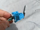
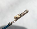
lastly, I spent a fair amount of time trying to figure out what to do about the cruise module pigtail - I really don't want to splice it into my harness, partly because I can't locate DJ-453 crimp splices in the smaller than .03mm size I need. So the plan was to re-pin my wiring with the appropriate 040 terminals into the 14pole housing. The problem is, I can't identify the terminals, they don't match anything I have a listing for (of course). EDIT 8/22- CorsaTechnic identified them as MX5.040 series terminals, which are not available OEM. What I will likely have to do is add another male/female connection from the pigtail to the harness

PXL_20220811_144315762.jpg PXL_20220811_144231384.jpg
 
Last edited:
Yesterday I wrapped up most of the wiring in the spare well area. Took care of the cruise module bridge harness using a YZ housing & terminals:

PXL_20220812_132919714.jpg


PXL_20220812_133319980.jpg


PXL_20220812_151112719.jpg


Another cruise related concern - the connector positions for the actuator & control panel are labelled from the male terminals - I had to go back & reverse the wire order in the actuator housing, as the markings on the Denso housing are reverse order (L-R: 4-1, vs. 1-4)

PXL_20220812_140827624.jpg


as I had wired them (incorrect for Honda wiring)
PXL_20220812_140807285.jpg


the control panel I'll deal with when I do the dash end wiring later - that one is awkward as there is a 3 pole bridge adaptor (not shown) that the 4pole connects to, and the wire colors don't match any schematic.

PXL_20220812_140831645.jpg

Last major item was the 8 pole power supply I had added, at the time I didn't have a heavy duty crimp tool or the ideal terminal/housings, so I had spliced this one in....
PXL_20220812_155856869.jpg


...cut that out & used terminals sourced from Eastern Beaver or Cycle Terminal, I forget which. The gauge of these terminals requires the bolt-cutter size crimp tool also used for battery crimps . Added the (orn-bl) supply alongside the pnk/blk to the new +15 fuse panel.
PXL_20220812_165007979.jpg


last item here is the overly long 2 pole starter harness (hanging out into access opening)- waiting for Yazaki 6.3 terminals from Mouser so I can cut out the splice & re-pin that neatly.
PXL_20220812_183600366.jpg
 
Last edited:
Back
Top