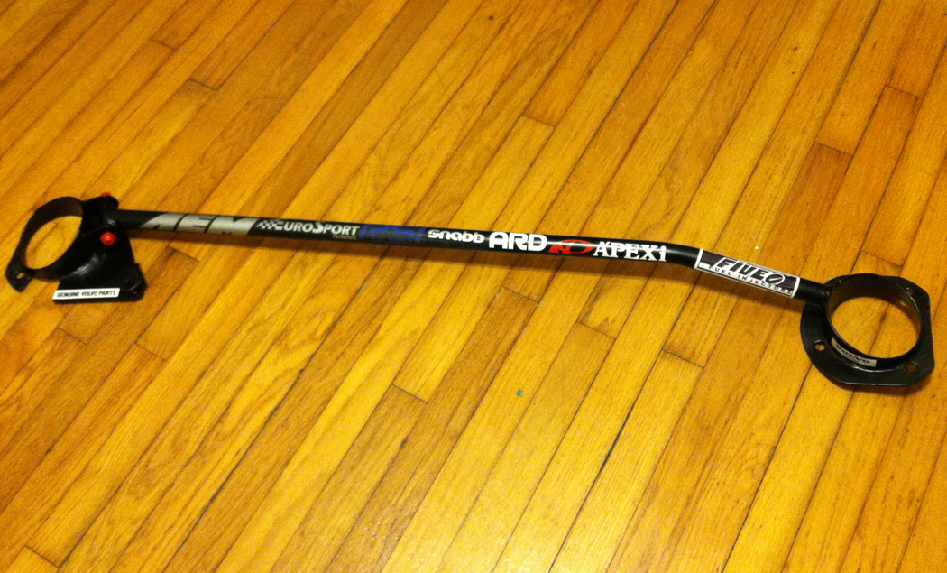
One thing though - don't you NOT want to bolt the braces in place in the direction of potential load? Won't they (the sections) just flex at those junctions rather than add rigidity? Or will they have double bolts or locating pins, etc?

Interesting...

I'm not 100% sure where you're going. I see two functions with this solution:

1. act as your typical strut bar: tie the two strut towers together (when the high-load outer tower is mid-corner, the stress of pull is transmitted to the less-loaded inner tower)
2. extend the strut brace to a second front bulkhead via the triangulation and tie-in of the load to the center tunnel

I need a longer explanation of your question Hussein - I honestly don't understand what you're aiming at. Which section is flexing? Where don't I want to brace? Please do further comment.
 
My understanding is that (most strut bars) aren't actually doing much of anything in terms of structural reinforcement, when the design used simply bolts components (especially flat stock) together, with single point mounting (to chassis, tower, etc.,) or axis point attachments. With that type of design, flex in the chassis will likely just flex the junction of the brace rather than spread load/flex out over the chassis, as I understand it. Of course, you can test it with a assembled car by lifting one corner while observing the bracing, not clear how you could test that effectively with a stripped chassis.

The old strut brace I had used tubular stock welded on one side, a flange that bolted to the strut tower with a vertical collar that the stay actually attached to, and had a double ear flange on the one side that was bolted.

Only pic I can find now, not so clear but you get the idea, in this fashion as much load/flex is spread across the chassis as is possible.

V70-XR-0495.jpg


So, perhaps at least double ear welded brackets on the chassis, with a separate set of tabs for the triangulating bars, rather than overlapping attachment as is your illustration?
 
I spent a lot of time looking at the front-top of the tunnel where it attaches to the bulkhead as probably the primary weak point of the chassis - certainly the center tunnel.
View attachment 12431

See, if it's not a box, then it isn't really doing much. The center-console braces running up provide some torsional rigidity as they're attached to the center tunnel where it's still a full box and connected to a very strong cross member just under the dash, which itself is connected the strong verticals in front of the doors and a large box section running from your strut towers thru the bulkhead and into the dash. On the early models, they were narrow. On the later ones I've noticed they're quite a bit wider at the top where they connect to the dash frame so maybe Bertone fixed it that way. Here's mine and then Rodgers' (cuz I found a picture of a naked car)
View attachment 12435 View attachment 12436


To convince myself, I found a longish rectangular box and checked for torsion (twist). Pretty strong. Next, cut out the end of a section like the exxe has and - WOW. twisted like crazy. Noticing that the top panel wants to put lateral force at where it would otherwise be attached to the front bulkhead, of course one thinks "weld it up" since I have a welder. Problem is that you wouldn't be able to ever remove your wiring harness, heater tubes, get to your throttle cable connection etc. It is nice having that area and you can get to it without taking the carpet out. So instead I thought about adding a bolted cover to the tunnel and tried it with the cardboard box.
View attachment 12442 View attachment 12443

That worked really well. So I cut the cover out of some cold rolled sheetmetal and added a short lateral section to bolt to the front with (welded to the car) - here's a photo but it's not in focus.
View attachment 12444
Where it attaches to the solid part of the tunnel a bit further back, just 4 flat-top bevel style bolts (to hold it from sliding) and weld-nuts attached to the tunnel.
View attachment 12445 View attachment 12446


I did try take a video to try and demonstrate it but it didn't work out as I don't have a tripod and had to hold the camera. It's pretty easy to do yourself with a cardboard box and a knife tho.

I sure wish I had a jig to test chassis deflection so I could see how much it helps (didn't I see a post here of someone doing just that?). If it helped a lot, it'd be a super easy mod to any exxe without taking much off: just the cover under the heater, pull back the carpet a bit bolt it on with rivnuts. Just need someone to make a kit! (not me).

Missed this gem last time around.

I'm going to add a piece along these lines, especially as I will be removing / reworking the existing center console braces.

index.php
 
Missed this gem last time around.

I'm going to add a piece along these lines, especially as I will be removing / reworking the existing center console braces.

index.php

I would suggest keeping as much of a top flange on the original tunnel as is reasonable. The cover piece pictured would also benefit from flanges that wrap over the side of the existing tunnel and make your fastenings along the vertical face of the cover into the side face of the tunnel with periodic connections into the remaining top face of the surfaces of the tunnel. I would also go up a gauge to provide a better surface to attach the shift mechanism to.
 
I would suggest keeping as much of a top flange on the original tunnel as is reasonable. The cover piece pictured would also benefit from flanges that wrap over the side of the existing tunnel and make your fastenings along the vertical face of the cover into the side face of the tunnel with periodic connections into the remaining top face of the surfaces of the tunnel. I would also go up a gauge to provide a better surface to attach the shift mechanism to.

This is the foremost area of the tunnel where it meets the bulkhead - it's completely open from the factory - not the shifter area :)

index.php
 
This is the foremost area of the tunnel where it meets the bulkhead - it's completely open from the factory - not the shifter area :)

index.php

In the words of Roseanne Rosannadana, Nevermind...

My apologies I was thinking the whole length was opened up.

If you are going to close that up with relief for the pipes, I would center the pipes and make the opening on the centerline and add a flange that goes up the front firewall. My previous comments about fastening stand.
 
The cover piece pictured would also benefit from flanges that wrap over the side of the existing tunnel and make your fastenings along the vertical face of the cover into the side face of the tunnel with periodic connections into the remaining top face of the surfaces of the tunnel.
IMG_2707.jpg
IMG_2708.jpg


It's like you read my mind from last month! I agree on the side flange for the primary purpose of managing shear and controlling horizontal flex. I also found that I needed to increase the material depth for the bevel bolts to provide better more control. The material is not thin - it is 14G or 0.0747 cold rolled steel - but not enough for bolting, so I doubled it underneath on the top bolts. Oh, and all the bolts thread into weld nuts that are welded on the tunnel.

IMG_2774.jpg
IMG_2775.jpg
IMG_2776.jpg


I know those welds look pretty ugly on the flanges, but it's not weld: I have a silicon bronze MIG spool gun setup on my TIG and was trying it out. Less heat effect and thus less chance of warpage.
If I did it again, I'd simply use aluminum like I did for the rear engine access panel or the spare-tire access panel covers, but this should work.

The access for the heater tubes and center tunnel wiring are there and the other good reason to make the cover removable is to service the throttle.

Glad you like it. Thanks for checking it out.
 
I have not followed this thread religiously but is there a reason why the dash brace between the tunnel and the dash cross brace was removed? Sure makes access in that area 100 times easier.
 
I have not followed this thread religiously but is there a reason why the dash brace between the tunnel and the dash cross brace was removed? Sure makes access in that area 100 times easier.

It is not removed, just some clever photography on my part to omit that from the shots I guess. See this image from the initial post on this thread:

IMG_2031 (1).JPG


IMO that brace (center console?) does reinforce the chassis but more from an up/down "banana" flex POV. It would help in resisting chassis twist but only slightly. Definitely keeping in in there tho.
 
Darin, depending on what will be going back into the vertical console. What about covering the front open area with a metal panel (box it in) to increase the rigidity more? It might help with the overall flex, similar to how reinforcing the rear panel (behind the seats) did, but likely a little less so:

IMG_2031 (1).JPG
 
Hi Jeff. Yeah, that makes sense and I did think about that (briefly) but I'm not building a race car - I'm building a street ride that's stiff like a Mercedes Benz (that is my silly boy dream anyways). I agree that would work but then getting the center console with the switch gear, heater controls and sweet Italian ashtray there would be near impossible and horrible to service.

Instead, just make the tunnel super tough and go all the way up to the front firewall and you're good. Chassis really is very stiff stock as we all know - at least for a targa/convertible.
 
Got Addco swaybars (front and rear). Figured I'd improve the mounting of it. Front inspired by Mark Plaia's setup, rear I kind of rolled my own. For background, here's a good video from @TonyK (I think) that outlines the stock setup:

Front:
IMG_3677.JPG

IMG_3675.JPG


IMG_3674.JPG


IMG_3673.JPG


Rear:
IMG_3678.JPG


IMG_3595.JPG


IMG_3596.JPG


In addition to having a stronger mount for the rear bar, I dropped some weight: 675g (24oz) to 410g (14.5oz)
IMG_3204.JPG

IMG_3681.JPG


IMG_3205.JPG
 
Last edited:
Nice job. ;) I've never been too fond of the way most sway bars mount on the X. Your approach is much better.

I used to think having multiple mounting points for the links (to change the bar's rate) would not have much effect on a street car. But when I started experimenting with them on a BMW many years ago, I found there really was a noticeable difference in the handling depending on the bar's setting. To be honest, that car's suspension had all of the usual upgrades so it might not be considered "stock". But after feeling the effects of changing the bars on it, I was able to recognize the differences it also made on other (more stock) cars.

On the subject of sway bars, I find it interesting that there is such a mixed view about their use on the X. With both bars vs none, or just front or just rear bar, etc. I'm looking forward to hearing how your whole project results with them in connection to all of the other chassis upgrades you are making. :)
 
Last edited:
What OD are the addco bars? I'm glad I already have mine in front, since MWB says it's essential for Honda conversion. Not sure I want to fiddle with a rear bar. Maybe I'll wait until you or Rodger provide some handling reviews
 
The rear bar will tend to lift the inside rear tire.
Wo if you have a bunch of power and no LSD, you might create a lot of smoke.
I would just try it with and without the bar connected.
 
Has there been a summary written up to describe the effects of bars vs no bars, front vs rear, combined with different spring rates, etc?
 
Put a WaveTrac LSD in the Honda transaxle. I've read just the front one in needed, but in the chance I wanted to loosen up the back end a bit, wanted that ability. Since the Addco setup is so wanky (on the rear especially) I figured if I really don't want it, it can be easily removed. The config pictured is at it's weakest setting now. The original design was to have the brackets that bolt to the A-arms have 3 different mount holes. There wasn't enough area in the mount (I made it from 1"x1" box steel) to allow the link to sit above the bolts.

One small redesign will be to change from individual bolt holes to a slotted mount - both on the bar-end as well as the A-arm brackets. All the way forward on the bar and all the way toward the inside on the A-arms would be lightest setting.
 
I don't really have a general K20 resto-mod build thread so putting this in here...

I needed to rebuild my pedal box on the ’76 X1/9 just like seemingly everyone else on this forum. There are so many good resources here on Xweb like Bernice’s ’74 Pedal Box Project – Part 1 and Part 2 as well as some others. First up I needed to strip it and paint it. These cars and pedal boxes are so old they’re all gonna be rusty no matter what, so strip it down and paint it. I didn’t take photos, but you all know how that goes. I had bought a new brake and clutch master from MWB but ended up upgrading the brake MC to the “performance” one which is a bit larger and should match better with the larger Vick’s front calipers and 124 Spider rears from Autoricambi.

The plastic pedal thingy was all messed up. Inspired by Bernice’s post I decided to use a piece of scrap Delryn and shape it on the lathe. I don’t have a good deep boring bar for my lathe setup so I used a 9/16” drill bit which is very close to her stated spec. It was tighter than the stock piece I was removing tho. For my lathe I had to start with a short bit then use a long one but it worked out. Trim the outer to spec and cut to length.
IMG_5899.JPG


IMG_5900.JPG


IMG_5901.JPG


I don’t have a slitting saw or a tiny end mill that’s the required 0.110” (or smaller) width so I used a small drill bit in the mill and used it like and end mill bit. Worked ok.
IMG_5906.JPG


IMG_5904.JPG


The pressed in studs for the pedals were all messed up on my kit, at least for the clutch – the brake one was fine. I decided to replace that with an M12 bolt machined to replace the original. I needed to relocate it anyways for the K20 setup which has a smaller slave cylinder, and the easy fix is to reduce the throw at the pedal by relocating the pivot. Grind the inner shoulder off and it presses out.
IMG_5928.JPG


The M12 bolt and nut go to the lathe to get trimmed. The bolt head and the nut need to be thinner and the threads cut. You'll notice that an M12 bolt is very close to the size I needed on the pin. I actually wanted to do a 1.25 metric pitch on an M12 (i.e., a fine thread) but I only had a 1.75 pitch tap and no stores nearby had them. The current solution works and I'm not sure a finer pitch would cut smooth on those threads. If anyone has ideas on a method of filling I'd be interested.
IMG_5932.JPG


I’m super happy I re-read Rodgers post about how he needed to extend the push rod – I know why that happened now because I almost did the same thing! I figured the smart way to relocate it was to use the same axis from the pedal pivot but that isn’t right – you wanna shorten the total throw AND keep the rod closer to the clutch master cylinder at rest, so with the pin on the master cylinder you rotate the prescribed ½” closer to the pedal pivot. Happily the shape of the pedal is perfect for the new location. Hard to explain – hope the pictures help. Drilled and tapped for the M12 bolt.
IMG_5933.JPG


IMG_5934.JPG


It's not completely done - I need to disassemble again and prep/paint the pedals and maybe the box again but all the modifications work is done. Oh, and since someone will notice and ask:
1. The bit of metal that holds the hoses snapped off so I made a new one and bolted it
2. The retaining clip (painted yellow) gets a proper M5 SS bolt instead of the ridiculous Phillips head screw that rusts right away
3. my depth of cut for the slot must've been a bit deeper than prescribed. I can make a larger retainer (yellow thing) or use a neoprene ring. Idea for me is not only to keep the plastic bushing from sliding out but also to keep it from rotating in the pedal box housing. I think that's what ends up chewing the outside of it up.
IMG_5936.JPG


IMG_5938.JPG


IMG_5939.JPG


IMG_5940.JPG
 
I really like the work you have done, however, I would think about redoing the hard points on the front roll bar. That area of metal you choose (beside the radius rod mount) is really thin. I have ripped the radius rod mounts from the metal in this area before. Maybe put a plate under it, then sandwich it into the Frunk with some bolts? It's hard as there is a space between the metal on the floor and the metal in the trunk.

Otherwise, it is looking great.

I do agree with outers, I would ditch the rear bar for now. But, then again it is not my car, is it! ;)
 
Back
Top